Smart Doorbell with ESP-NOW Protocol: DIY Project (Guide)
Imagine a smart doorbell that works even when your internet goes down. No cloud dependencies, no Wi-Fi outages—just two ESP boards talking directly to each other, instantly. That’s exactly what we’re going to build today using ESP-NOW, Espressif’s incredibly efficient wireless protocol.
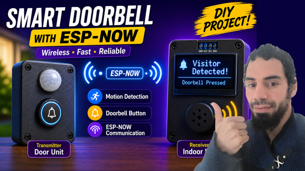
Here’s what our smart doorbell system will do:
- Motion detection alerts you to visitors
- Doorbell button rings the chime inside
- OLED screen displays the status
- Buzzer provides audio feedback
- Wireless communication uses ESP-NOW for instant, reliable transmission
Let’s get building!
What You’ll Need
Software
Before we dive into the code, you will need:
- Arduino IDE: Installed on your computer.
- The ESP32 and ESP8266 board packages are installed in your IDE.
If you’re completely new to the ESP32, I recommend checking out my previous blog post, an Ultimate ESP32 Beginner’s Guide. We’ve covered the basics of setting up your development environment, installing board support, and uploading your first program.
Hardware
| Component | Quantity |
|---|---|
| ESP32 or ESP8288 Development Board | 2 |
| OLED Display (SSD1306 I2C) | 1 |
| PIR Motion Sensor | 1 |
| Push Button | 1 |
| Active Buzzer | 1 |
| Breadboards | 2 |
| Jumper Wires | Several |
| USB Cable | 2 |
Project Overview
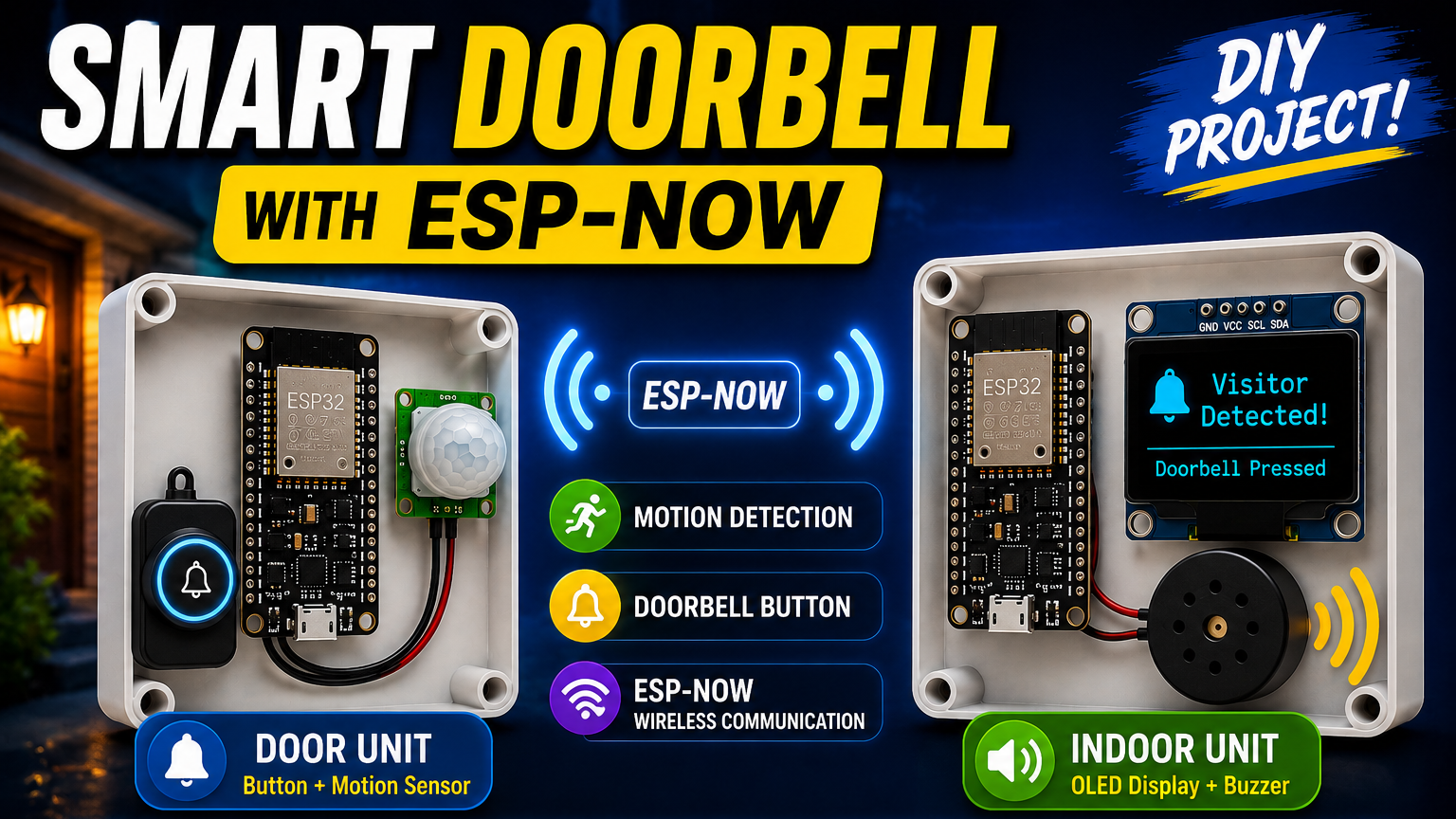
This project consists of:
- A Doorbell Unit installed outside the house.
- A Receiver Unit located inside the house.
When someone presses the doorbell button or stands near the door, the outdoor ESP board instantly sends a wireless message to the indoor ESP32 using ESP-NOW. The receiver displays the event on an OLED screen and activates a buzzer to alert the homeowner.
The entire communication occurs without a Wi-Fi router or Internet connection, making the system extremely fast and reliable.
Step 1: Getting Your MAC Addresses
Each ESP board has a unique MAC address. We need the receiver’s MAC address to establish communication. Upload this sketch to each board and note the output:
#ifdef ESP32
  #include <WiFi.h>
#else
  #include <ESP8266WiFi.h>
#endif

void setup() {
  Serial.begin(115200);
  WiFi.mode(WIFI_STA);
  delay(2000);
  Serial.println("MAC Address: ");
  Serial.println(WiFi.macAddress());
}

void loop() {
  delay(1000);
}
Open the Serial Monitor at 115200 baud, then reset the board, and you’ll see the MAC address displayed.
MAC Address:
CC:50:E3:04:EF:37
You’ll need the receiver’s MAC address in the transmitter’s code, and vice versa, if you want two-way communication.
Step 2: Circuit Diagrams (Wiring)
Our smart doorbell splits into two units:
Transmitter (Door Unit)
Receiver (Indoor Unit)

Step 3: Transmitter Code
The transmitter sends data when the button is pressed or motion is detected. We’ll use a simple struct to package our message :
#ifdef ESP32
#include <WiFi.h>
#include <esp_now.h>
#else
#include <ESP8266WiFi.h>
#include <espnow.h>
#endif

// Replace with your receiver's MAC address
uint8_t receiverMac[] = {0x3c, 0x8a, 0x1f, 0x9c, 0x99, 0x70};

// Message structure
typedef struct {
  uint8_t type;    // 0 = button press, 1 = motion detected
} DoorbellMessage;

DoorbellMessage msg;

// Button and motion pins
const int buttonPin = D3;
const int motionPin = D6;

void setup() {
  Serial.begin(115200);

  // Initialize pins
  pinMode(buttonPin, INPUT_PULLUP);
  pinMode(motionPin, INPUT);

  // Set up Wi-Fi in station mode
  WiFi.mode(WIFI_STA);

  // Initialize ESP-NOW
  #ifdef ESP32
  esp_now_init();
  #else
  WiFi.disconnect();  // IMPORTANT: Prevents auto-connect issues on ESP8266
  esp_now_init();
  #endif

  // Add peer (receiver)
  #ifdef ESP32
  esp_now_peer_info_t peerInfo;
  memcpy(peerInfo.peer_addr, receiverMac, 6);
  peerInfo.channel = 0;
  peerInfo.encrypt = false;
  if (esp_now_add_peer(&peerInfo) != ESP_OK){
    Serial.println("Failed to add peer");
    return;
  }
  #else
  // Set role for ESP8266 (must be done before adding peer)
  esp_now_set_self_role(ESP_NOW_ROLE_CONTROLLER);
  // Add peer (ESP8266 version - different parameters)
  if (esp_now_add_peer(receiverMac, ESP_NOW_ROLE_SLAVE, 1, NULL, 0) != 0){
    Serial.println("Failed to add peer");
    return;
  }
  #endif
}

void loop() {
  bool buttonPressed = digitalRead(buttonPin) == LOW;
  bool motionDetected = digitalRead(motionPin) == HIGH;

  if (buttonPressed) {
    msg.type = 0;
    sendMessage();
    delay(500); // Debounce
  }

  if (motionDetected) {
    msg.type = 1;
    sendMessage();
    delay(3000); // Prevent multiple triggers
  }

  delay(100);
}

void sendMessage() {
  #ifdef ESP32
  esp_now_send(receiverMac, (uint8_t*)&msg, sizeof(msg));
  #else
  esp_now_send(receiverMac, (uint8_t*)&msg, sizeof(msg));
  #endif
  Serial.println("Message sent!");
}
Step 4: Receiver Code
The receiver listens for incoming ESP-NOW messages and responds accordingly :
#ifdef ESP32
#include <WiFi.h>
#include <esp_now.h>
#else
#include <ESP8266WiFi.h>
#include <espnow.h>
#endif

#include <Wire.h>
#include <Adafruit_GFX.h>
#include <Adafruit_SSD1306.h>

// OLED display setup
#define SCREEN_WIDTH 128
#define SCREEN_HEIGHT 64
#define OLED_ADDRESS 0x3C

Adafruit_SSD1306 display(SCREEN_WIDTH, SCREEN_HEIGHT, &Wire, -1);

// Message structure (must match transmitter)
typedef struct {
  uint8_t type;
} DoorbellMessage;

DoorbellMessage receivedMsg;

// Buzzer pin
const int buzzerPin = 27;

void setup() {
  Serial.begin(115200);

  // Initialize OLED
  if(!display.begin(SSD1306_SWITCHCAPVCC, OLED_ADDRESS)) {
    Serial.println("OLED allocation failed");
  }
  display.clearDisplay();
  display.setTextColor(SSD1306_WHITE);

  // Initialize buzzer
  pinMode(buzzerPin, OUTPUT);

  // Set up Wi-Fi
  WiFi.mode(WIFI_STA);

  // Initialize ESP-NOW
  #ifdef ESP32
  esp_now_init();
  esp_now_register_recv_cb(esp_now_recv_cb_t(onDataReceived));
  #else
  WiFi.disconnect();  // Important for ESP8266
  esp_now_init();
  esp_now_set_self_role(ESP_NOW_ROLE_SLAVE);
  esp_now_register_recv_cb(onDataReceived);
  #endif

  displayMessage("Ready", "Doorbell Waiting...");
}

void onDataReceived(uint8_t* mac, uint8_t* data, int len) {
  memcpy(&receivedMsg, data, sizeof(receivedMsg));

  Serial.print("Received from MAC: ");
  for(int i = 0; i < 6; i++) {
    Serial.print(mac[i], HEX);
    if(i < 5) Serial.print(":");
  }
  Serial.println();

  if(receivedMsg.type == 0) {
    // Doorbell button press
    displayMessage("DOORBELL", "Someone at the door!");
    ringBuzzer(3);
  } else if(receivedMsg.type == 1) {
    // Motion detected
    displayMessage("MOTION", "Movement detected!");
    ringBuzzer(1);
  }
  delay(1000);
  displayMessage("Ready", "Doorbell Waiting...");
}

void ringBuzzer(int times) {
  for(int i = 0; i < times; i++) {
    digitalWrite(buzzerPin, HIGH);
    delay(300);
    digitalWrite(buzzerPin, LOW);
    delay(300);
  }
}

void displayMessage(String line1, String line2) {
  display.clearDisplay();
  display.setTextSize(2);
  display.setCursor(0, 10);
  display.println(line1);
  display.setTextSize(1);
  display.setCursor(0, 40);
  display.println(line2);
  display.display();
}

void loop() {
  // You can add additional logic here (e.g., timeouts, additional displays)
  delay(100);
}
Step 5: Testing and Troubleshooting
Common Issues:
1. Devices not communicating
- Double-check the MAC address in the transmitter code
- Ensure both boards are powered
- Verify the receiver’s Wi-Fi is in STA mode
2. Button not responding
- Check your pull-up resistor wiring
- Try a different GPIO pin
- Add a debounce delay if triggering multiple times
3. OLED display blank
- Verify I2C connections (SCL and SDA)
- Check the I2C address (0x3C or 0x3D)
- Install required libraries (Adafruit_GFX, Adafruit_SSD1306)
4. Motion sensor false triggers
- Adjust the sensitivity potentiometer on the PIR module
- Add a longer delay between readings
Taking It Further
Your smart doorbell is just the beginning! Here are some ways to expand this project :
Add Encryption
ESP-NOW supports encrypted communication for enhanced security :
#ifdef ESP32
peerInfo.encrypt = true;
#endif
Two-Way Communication
Modify the receiver to send acknowledgments back to the transmitter, confirming the message was received.
Battery-Powered Door Unit
Optimize the transmitter for low power:
esp_deep_sleep_enable_timer_wakeup(1000000); // Wake every second
esp_deep_sleep_start();
This can extend battery life to months or even years.
Home Assistant Integration
Connect the receiver to Home Assistant using MQTT or serial communication to create a full smart home doorbell system.
Visual Feedback
Add an RGB LED to the receiver to indicate connection status or different alert types.
Final Thoughts
Building this smart doorbell with ESP-NOW is a perfect introduction to wireless IoT projects without the dependency on Wi-Fi networks. The direct communication between boards ensures instant response times, making it a reliable solution for your home.
The best part? You now understand the fundamentals of ESP-NOW—a skill that opens doors to countless other projects. Want to build a wireless temperature sensor network? A smart garden monitor? An offline security system? They all follow the same pattern you’ve learned here.
Happy building! If you run into issues or have ideas for improvements, the online ESP community is incredibly helpful. Remember to share your project and inspire others to go wireless with ESP-NOW!