Build Your Own Real-Time Clock with Arduino, LCD, and Keypad Matrix
Keeping accurate time is an essential feature in many electronics projects. Whether you’re building a home automation system, attendance tracker, alarm clock, or scheduling devices.
A Real-Time Clock (RTC) module allows your project to maintain the correct date and time even when power is removed.
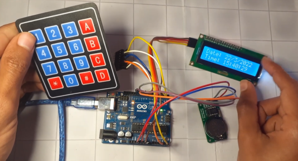
In this tutorial, we will build a complete Arduino Real-Time Clock using the DS1302 RTC module, a 16×2 I2C LCD, and a 4×3 matrix keypad. The LCD continuously displays the current date and time, while the keypad allows you to manually update the clock whenever needed.
Components Required
To build this project, you will need the following components:
- Arduino Uno (or compatible board)
- LCD Display 16×2 (with I2C adapter – highly recommended to save pins)
- 4×3 or 4×4 Keypad Matrix
- DS1302 Real-Time Clock Module
- Jumper wires
- Power supply
I highly recommend getting a complete starter kit that includes everything you need to create a wide range of projects.
Circuit Connections
Here’s how to connect everything:
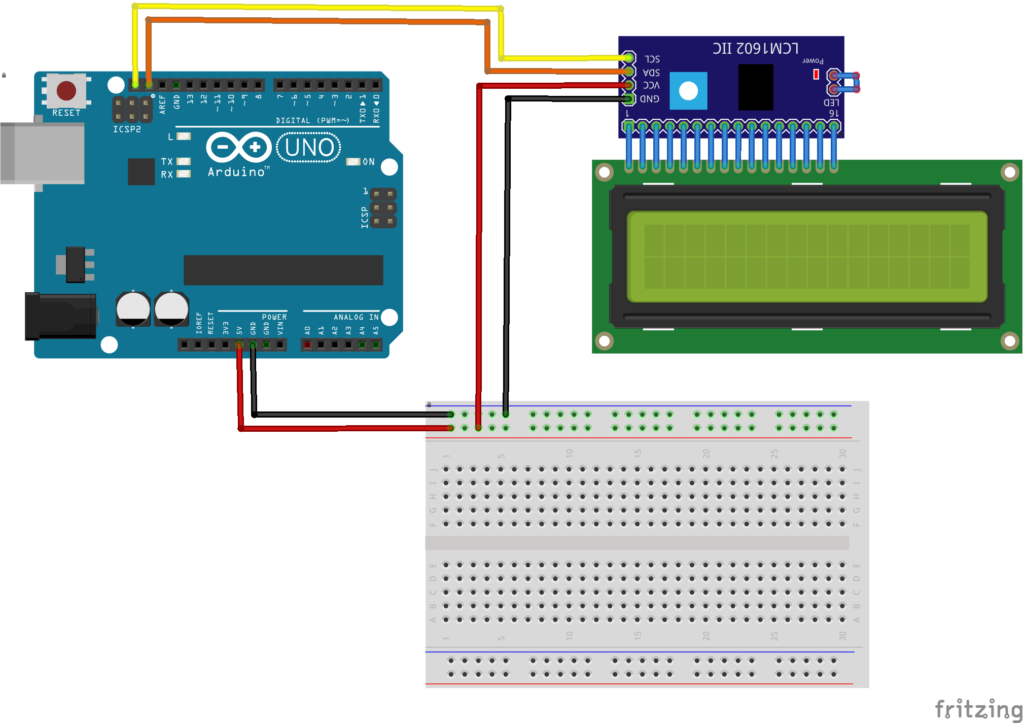
LCD (I2C)
- VCC → 5V on Arduino
- GND → GND
- SDA → A4 (on Uno)
- SCL → A5 (on Uno)
Note: If your LCD doesn’t work, try changing the I2C address from 0x3F to 0x27 — common addresses for these modules.
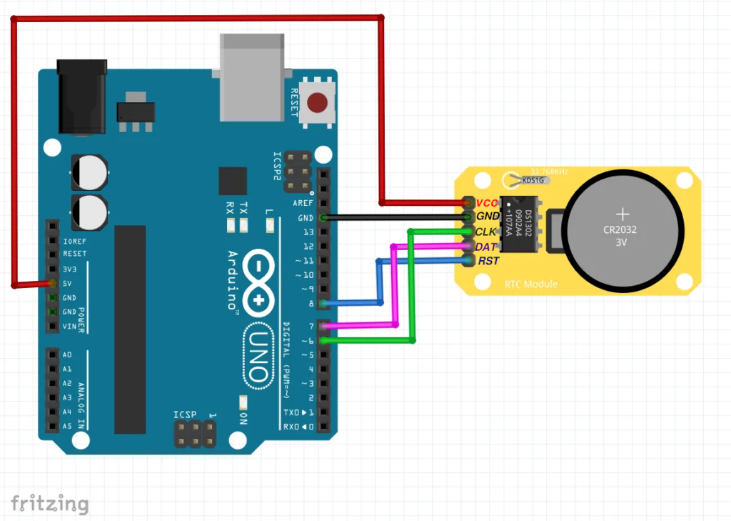
DS1302 RTC Module
- DAT → Pin 11
- CLK → Pin 10
- RST → Pin 12
- VCC → 5V
- GND → GND
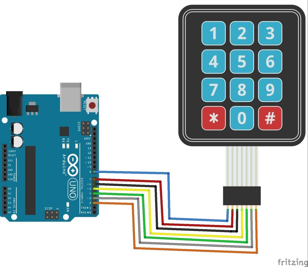
4×3 Keypad
- Rows → Pins 9, 8, 7, 6
- Columns → Pins 5, 4, 3
The Complete Code
Here’s the final code I used for this project. It reads the current time from the DS1302, displays it on the LCD, and lets you update the time by pressing the * key:
#include <LiquidCrystal_I2C.h>
#include <ThreeWire.h>
#include <RtcDS1302.h>
#include <Keypad.h>

const byte ROWS = 4; //four rows
const byte COLS = 3; //four columns
//define the cymbols on the buttons of the keypads
char hexaKeys[ROWS][COLS] = {
  {'1', '2', '3'},
  {'4', '5', '6'},
  {'7', '8', '9'},
  {'*', '0', '#'}
};
byte rowPins[ROWS] = {9, 8, 7, 6}; //connect to the row pinouts of the keypad
byte colPins[COLS] = {5, 4, 3}; //connect to the column pinouts of the keypad

//initialize an instance of class NewKeypad
Keypad customKeypad = Keypad( makeKeymap(hexaKeys), rowPins, colPins, ROWS, COLS);

//0x3F or 0x27
LiquidCrystal_I2C lcd(0x3F, 16, 2);   //LCD Object

ThreeWire myWire(11, 10, 12);        // DAT, CLK, RST
RtcDS1302<ThreeWire> Rtc(myWire);    // RTC Object

void setup ()
{
  lcd.init();
  lcd.backlight();
  lcd.clear();

  Rtc.Begin();

  //RtcDateTime currentTime = RtcDateTime(__DATE__ , __TIME__);
  //Rtc.SetDateTime(currentTime);
}

void loop ()
{
  RtcDateTime now = Rtc.GetDateTime();
  lcd.clear();
  lcd.setCursor(0, 0);
  lcd.print("Date: ");
  lcd.print(now.Day());
  lcd.print("/");
  lcd.print(now.Month());
  lcd.print("/");
  lcd.print(now.Year());

  lcd.setCursor(0, 1);
  lcd.print("Time: ");
  lcd.print(now.Hour());
  lcd.print(":");
  lcd.print(now.Minute());
  lcd.print(":");
  lcd.print(now.Second());

  //Set the Date and Time Manually when '*' key is pressed
  char c = customKeypad.getKey();
  if (c == '*') {
    lcd.clear();
    lcd.setCursor(0, 0);
    lcd.print("Enter Year: ");
    int year = getData();

    lcd.clear();
    lcd.setCursor(0, 0);
    lcd.print("Enter Month: ");
    int month = getData();

    lcd.clear();
    lcd.setCursor(0, 0);
    lcd.print("Enter DayOfWeek: ");
    int day = getData();

    lcd.clear();
    lcd.setCursor(0, 0);
    lcd.print("Enter Hours: ");
    int hour = getData();

    lcd.clear();
    lcd.setCursor(0, 0);
    lcd.print("Enter Minutes: ");
    int minute = getData();

    lcd.clear();
    lcd.setCursor(0, 0);
    lcd.print("Enter Seconds: ");
    int second = getData();

    RtcDateTime newTime = RtcDateTime(year, month, day, hour, minute, second);
    Rtc.SetDateTime(newTime);

  }

  delay(500);
}

int getData() {
  String container = "";
  lcd.setCursor(0, 1);
  while (true) {
    char c = customKeypad.getKey();
    if (c == '#') {
      break;
    } else if (isDigit(c)) {
      container += c;
      lcd.print(c);
    } else {
      //Nothing
    }
  }
  return container.toInt();
}
Before uploading the code, install these libraries via the Arduino Library Manager:
LiquidCrystal_I2Cby Frank de BrabanderRtcDS1302by MakunaKeypadby Mark Stanley, Alexander Brevig
How It Works
Displaying Time:
In loop(): The code fetches the current date and time from the RTC using Rtc.GetDateTime() and prints it to the LCD in DD/MM/YYYY and HH:MM:SS format.
Manual Time Setting:
When you press the * Key, the program enters setup mode. It asks you to enter:
- Year (e.g., 2025)
- Month (1–12)
- Day (1–31)
- Hours (0–23)
- Minutes (0–59)
- Seconds (0–59)
After each prompt, you type digits on the keypad and press the “#” sign to confirm. The getData() function collects the digits and returns them as an integer.
Once all values are entered, the RTC is updated with the new date and time.
First-Time Setup:
In the setup() function, I commented out the lines that set the RTC using the compile time:
//RtcDateTime currentTime = RtcDateTime(__DATE__ , __TIME__);
//Rtc.SetDateTime(currentTime);
If you want to set the RTC for the first time without using the keypad, uncomment those lines, upload the code once, then comment them again. After that, always use the keypad to adjust the time.
Code Explanation
Default Project Setup:
First, we create a 16×2 LCD object using the I2C address 0x3F:
//0x3F or 0x27
LiquidCrystal_I2C lcd(0x3F, 16, 2);   //LCD Object
Then we define the communication pins used by the DS1302 module:
ThreeWire myWire(11, 10, 12);        // DAT, CLK, RST
RtcDS1302<ThreeWire> Rtc(myWire);    // RTC Object
Now, in the loop, we retrieve the current date and time from the RTC Module:
RtcDateTime now = Rtc.GetDateTime();Next, we show the current time on the first LCD row and the date on the second row:
lcd.print(now.Day());
lcd.print("/");
lcd.print(now.Month());
lcd.print("/");
lcd.print(now.Year());
lcd.print(now.Hour());
lcd.print(":");
lcd.print(now.Minute());
lcd.print(":");
lcd.print(now.Second());Entering Setup Mode
When the user presses “*”, the Arduino begins collecting new date and time values.
if (c == '*')And this custom function:
int getData()- Reads keypad digits
- Displays entered values on the LCD
- Stores them in a string
- Converts the string into an integer
- Returns the result
The “#” key confirms the entered value.
Updating the RTC
    RtcDateTime newTime = RtcDateTime(year, month, day, hour, minute, second);
    Rtc.SetDateTime(newTime);
Finally, we create a new date/time object and store it inside the DS1302 module.
Troubleshooting
| Problem | Likely Fix |
|---|---|
| Check I2C address (try 0x27 or 0x3F). Adjust the contrast pot on the back. | Check I2C address (try 0x27 or 0x3F). Adjust contrast pot on the back. |
| RTC loses time on power-off | Install a CR2032 battery in the RTC module. |
| Keypad not responding | Double-check row/column pin mappings. |
| Garbage time values | Run the initial setup with __DATE__ __TIME__ once, then switch to keypad updates. |
Final Thoughts
This project is a great foundation for anything that needs reliable timekeeping — from an automatic pet feeder to a data logger or even a smart home controller. The ability to set the time without re-uploading code makes it practical and user-friendly.
I hope you enjoy building this clock as much as I did. Feel free to remix, upgrade, and share your version.
Happy making! 🕒