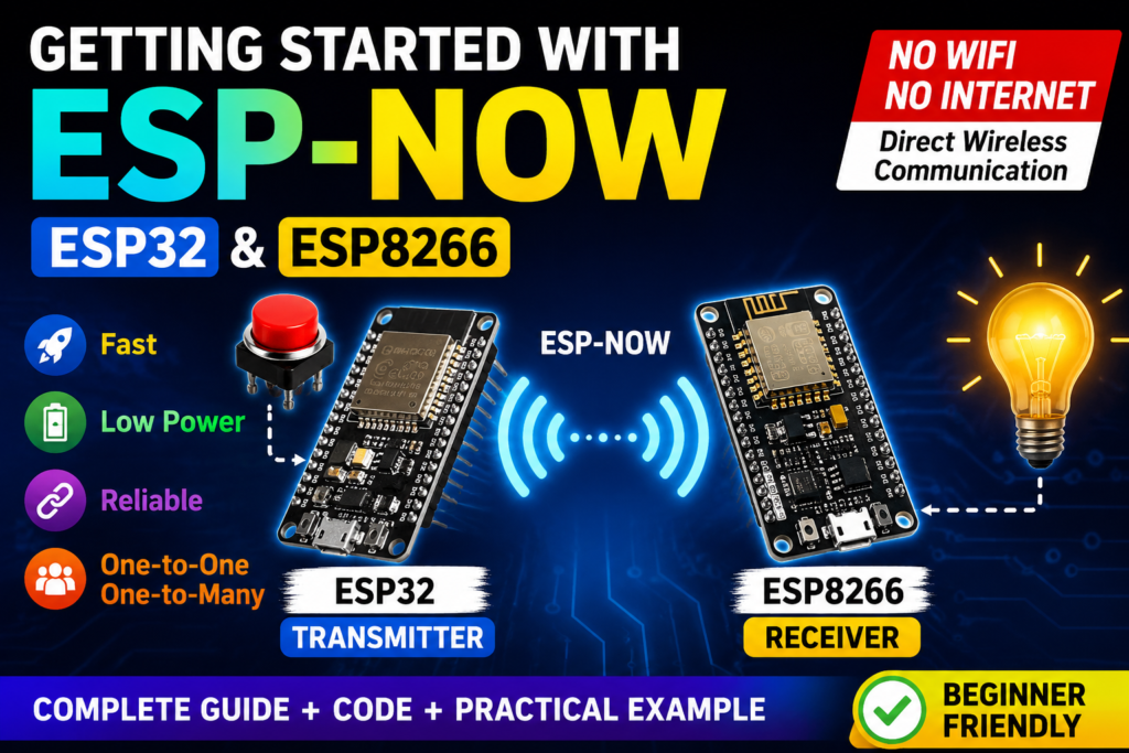
Learn ESP-NOW: Wireless Communication Between ESP Boards (ESP32 /ESP8266)
ESP-NOW is a highly versatile and lightweight wireless communication protocol developed by Espressif. Unlike standard Wi-Fi or Bluetooth, it allows multiple ESP32 and ESP8266 devices to exchange data directly without needing a router, internet connection, or complex network pairing.
This makes it perfect for IoT projects, sensor networks, home automation, robotics, and battery-powered devices.
In this comprehensive blog post, we will cover exactly how to configure your ESP32 and ESP8266 boards, retrieve their unique MAC addresses, and set up a basic one-way communication system where a Master (ESP32) sends a data packet to a Slave (ESP8266).
What is ESP-NOW?
ESP-NOW is a wireless communication protocol developed by Espressif Systems.
It allows multiple ESP devices to communicate directly with each other and exchange small data packets (up to 250 bytes) without connecting to a Wi-Fi network and with minimal latency.

Key Benefits
✅ No Router Required: Devices communicate directly using MAC addresses
✅ Low Power Consumption: Ideal for battery-powered devices
✅ Fast communication: Faster than TCP/IP communication
✅ Multiple Communication Modes: Supports one-to-one and one-to-many communication
✅ Support for Encryption: Secure communication between devices
✅ Ideal for IoT projects: Works with ESP32 and ESP8266
ESP32 vs ESP8266 Compatibility
Both ESP32 and ESP8266 support ESP-NOW, but there are important differences to note:
| Feature | ESP32 | ESP8266 |
|---|---|---|
| Maximum Peers | Up to 20 | More limited |
| Encryption Support | Full (up to 6 encrypted peers) | Limited stability |
| Role Management | Full flexibility | More restricted |
| Memory | Larger, supports more features | Code size restrictions apply |
For maximum compatibility between ESP32 and ESP8266, it’s recommended to use unencrypted communication.
How ESP-NOW Works
Instead of connecting devices through a Wi-Fi router, ESP-NOW creates a direct peer-to-peer connection and operates at the MAC layer, meaning devices communicate using their unique MAC addresses rather than IP addresses:
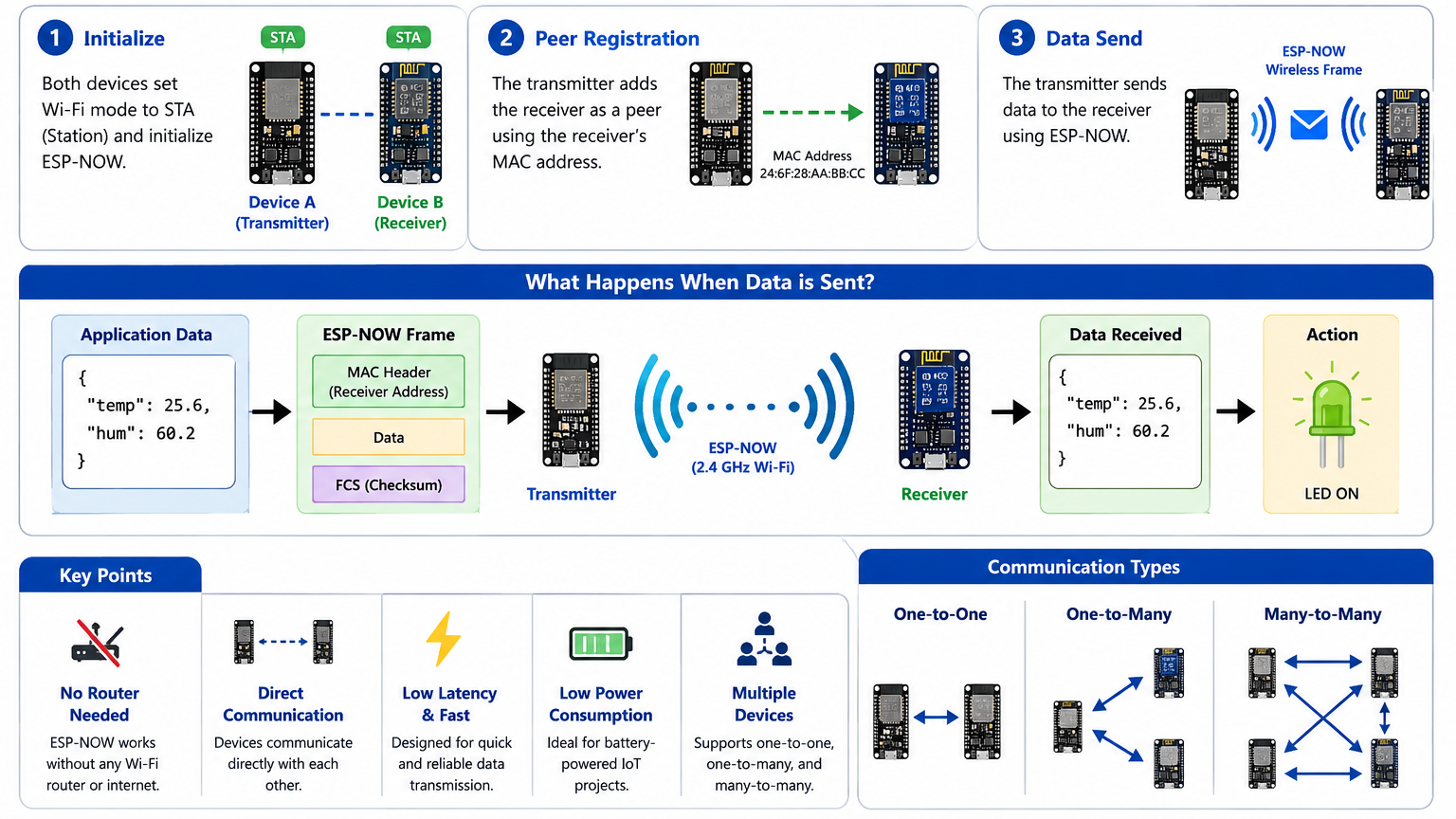
✅ This enables very fast and reliable wireless communication.
What You’ll Need?
Software
Before we dive into the code, you will need:
- Arduino IDE: Installed on your computer.
- The ESP32 and ESP8266 board packages are installed in your IDE.
If you’re completely new to the ESP32, I recommend checking out my previous blog post, an Ultimate ESP32 Beginner’s Guide. We’ve covered the basics of setting up your development environment, installing board support, and uploading your first program.
Hardware
For this tutorial, you need:
- ESP32 Development Board (any variant: ESP32 DevKit, NodeMCU-32S, etc.)
- ESP8266 (NodeMCU or Wemos D1 Mini)
- LED (for testing) & 220Ω resistor
- Potentiometer (10kΩ recommended)
- Breadboard (optional but recommended)
- Jumper Wires (male-to-female or male-to-male)
- Micro-USB Cables for programming and power
You can use either two identical ESP boards (such as two ESP32s or two ESP8266s) or two different boards (one ESP32 and one ESP8266), as ESP-NOW supports communication between both platforms, making it a flexible solution for a wide variety of IoT projects.
Project Overview
Now that you understand the basics of ESP-NOW, let’s build a practical project where you’ll control the brightness of an LED on one ESP device using a potentiometer on another ESP device. This is a perfect introduction to remote control applications!
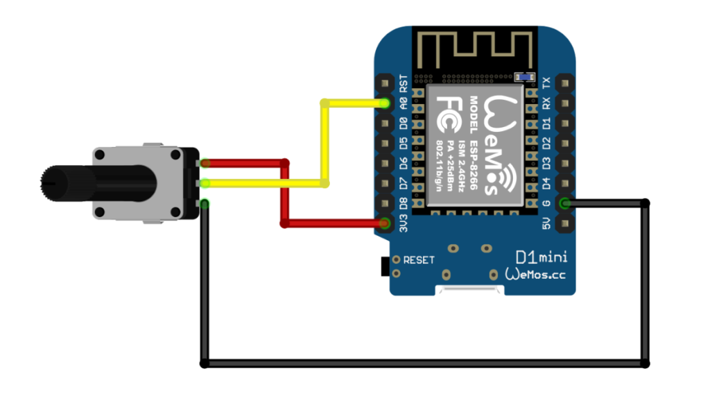
- Sender (ESP32/ESP8266): Reads analog value from a potentiometer and sends brightness levels via ESP-NOW
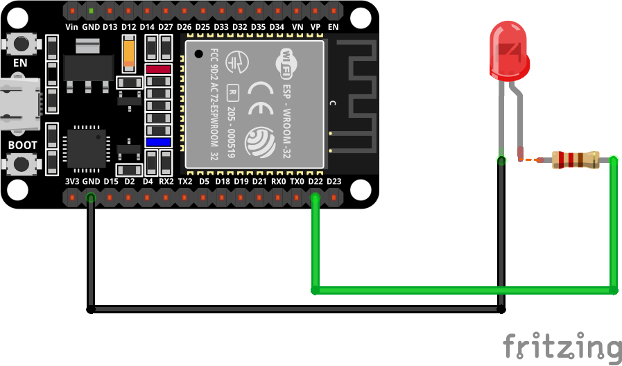
- Receiver (ESP32/ESP8266): Receives the brightness data and controls an LED using PWM
Circuit Diagrams
Transmitter Side:
Receiver Side:
Step 1: Get Your ESP Device’s MAC Address
Before you can send data, you need the MAC address of the receiving device.
Upload this sketch to your ESP device to get its MAC address:
#ifdef ESP32
  #include <WiFi.h>
#else
  #include <ESP8266WiFi.h>
#endif

void setup() {
  Serial.begin(115200);
  WiFi.mode(WIFI_STA);
  delay(2000);
  Serial.println("MAC Address: ");
  Serial.println(WiFi.macAddress());
}

void loop() {
  delay(1000);
}
Open the Serial Monitor at 115200 baud, then reset the board, and you’ll see the MAC address displayed.
MAC Address:
CC:50:E3:04:EF:37
Copy this address—you’ll need it for the sender sketch.
Step 2: Basic Communication Setup
Let’s build a simple one-way communication system: one ESP device sends data, and another receives it.
Sender Code (ESP32)
#include <WiFi.h>
#include <esp_now.h>

// Replace with your receiver's MAC address
uint8_t broadcastAddress[] = {0xCC, 0x50, 0xE3, 0x04, 0xEF, 0x37};

// Structure to send brightness data (SIMPLE - only brightness)
typedef struct struct_message {
  uint8_t brightness;  // 0-255
} struct_message;

// Create a struct_message called myData
struct_message myData;

// Potentiometer pin
const int potPin = 34;  // ESP32 ADC pin

esp_now_peer_info_t peerInfo;

// callback when data is sent
void OnDataSent(const uint8_t *mac_addr, esp_now_send_status_t status) {
  Serial.print("\r\nLast Packet Send Status:\t");
  Serial.println(status == ESP_NOW_SEND_SUCCESS ? "Delivery Success ✅" : "Delivery Fail ❌");
}

void setup() {
  // Init Serial Monitor
  Serial.begin(115200);
  pinMode(potPin, INPUT);

  // Set device as a Wi-Fi Station
  WiFi.mode(WIFI_STA);

  // Init ESP-NOW
  if (esp_now_init() != ESP_OK) {
    Serial.println("Error initializing ESP-NOW");
    return;
  }

  // Once ESPNow is successfully Init, we will register for Send CB to
  // get the status of Transmitted packet
  esp_now_register_send_cb(esp_now_send_cb_t(OnDataSent));

  // Register peer
  memcpy(peerInfo.peer_addr, broadcastAddress, 6);
  peerInfo.channel = 0;
  peerInfo.encrypt = false;

  // Add peer
  if (esp_now_add_peer(&peerInfo) != ESP_OK){
    Serial.println("Failed to add peer");
    return;
  }

  Serial.println("ESP-NOW Sender Ready!");
  Serial.print("Sender MAC Address: ");
  Serial.println(WiFi.macAddress());
}

void loop() {
  // Read potentiometer value (0-4095 on ESP32)
  int rawValue = analogRead(potPin);

  // Map to brightness (0-255)
  myData.brightness = map(rawValue, 0, 4095, 0, 255);

  // Send message via ESP-NOW
  esp_err_t result = esp_now_send(broadcastAddress, (uint8_t *) &myData, sizeof(myData));

  if (result == ESP_OK) {
    Serial.print("✅ Raw: ");
    Serial.print(rawValue);
    Serial.print(" | Brightness: ");
    Serial.println(myData.brightness);
  }
  else {
    Serial.println("❌ Error sending the data");
  }

  delay(100);  // Send updates 10 times per second
}
Sender Code (ESP8266)
#include <ESP8266WiFi.h>
#include <espnow.h>

// Replace with your receiver's MAC address
uint8_t broadcastAddress[] = {0x3c, 0x8a, 0x1f, 0x9c, 0x99, 0x70};

// Structure to send brightness data (SIMPLE - only brightness)
typedef struct struct_message {
  uint8_t brightness;  // 0-255
} struct_message;

// Create a struct_message called myData
struct_message myData;

// Potentiometer pin
const int potPin = A0;  // ESP8266 ADC pin (only A0)

// callback when data is sent (ESP8266 version)
void OnDataSent(uint8_t *mac_addr, uint8_t sendStatus) {
  Serial.print("\r\nLast Packet Send Status:\t");
  Serial.println(sendStatus == 0 ? "Delivery Success ✅" : "Delivery Fail ❌");
}

void setup() {
  // Init Serial Monitor
  Serial.begin(115200);
  pinMode(potPin, INPUT);
  delay(100);

  // Set device as a Wi-Fi Station
  WiFi.mode(WIFI_STA);
  WiFi.disconnect();  // IMPORTANT: Prevents auto-connect issues on ESP8266

  // Init ESP-NOW
  if (esp_now_init() != 0) {
    Serial.println("Error initializing ESP-NOW");
    return;
  }

  // Set role for ESP8266 (must be done before adding peer)
  esp_now_set_self_role(ESP_NOW_ROLE_CONTROLLER);

  // Register send callback (ESP8266 version - no cast needed)
  esp_now_register_send_cb(OnDataSent);

  // Add peer (ESP8266 version - different parameters)
  if (esp_now_add_peer(broadcastAddress, ESP_NOW_ROLE_SLAVE, 1, NULL, 0) != 0){
    Serial.println("Failed to add peer");
    return;
  }

  Serial.println("========================================");
  Serial.println("ESP8266 ESP-NOW LED Brightness Sender");
  Serial.println("========================================");
  Serial.print("Sender MAC Address: ");
  Serial.println(WiFi.macAddress());
  Serial.print("Receiver MAC Address: ");
  for (int i = 0; i < 6; i++) {
    Serial.printf("%02X", broadcastAddress[i]);
    if (i < 5) Serial.print(":");
  }
  Serial.println();
  Serial.println("========================================");
  Serial.println("Turn the potentiometer to control LED");
  Serial.println("========================================\n");
}

void loop() {
  // Read potentiometer value (0-1023 on ESP8266)
  int rawValue = analogRead(potPin);

  // Map to brightness (0-255)
  myData.brightness = map(rawValue, 0, 1023, 0, 255);

  // Send message via ESP-NOW
  uint8_t result = esp_now_send(broadcastAddress, (uint8_t *) &myData, sizeof(myData));

  if (result == 0) {
    Serial.print("✅ Raw: ");
    Serial.print(rawValue);
    Serial.print(" | Brightness: ");
    Serial.println(myData.brightness);
  }
  else {
    Serial.println("❌ Error sending the data");
  }

  delay(100);  // Send updates 10 times per second
}
Receiver Code (ESP8266)
#include <ESP8266WiFi.h>
#include <espnow.h>

// LED pin
const int ledPin = D4;

// Structure to receive brightness data
typedef struct struct_message {
  uint8_t brightness;
} struct_message;

// Create a struct_message called receivedData
struct_message myData;

// callback when data is received
void OnDataRecv(uint8_t * mac, uint8_t *incomingData, uint8_t len) {
  memcpy(&myData, incomingData, sizeof(myData));

  // Set LED brightness using PWM
  analogWrite(ledPin, myData.brightness);

  // Print received data (only every 10th packet to reduce spam)
  static int counter = 0;
  if (++counter >= 10) {
    counter = 0;
    Serial.print("Received brightness: ");
    Serial.println(myData.brightness);
  }
}

void setup() {
  // Init Serial Monitor
  Serial.begin(115200);
  pinMode(ledPin, OUTPUT);

  // Set device as a Wi-Fi Station
  WiFi.mode(WIFI_STA);
  WiFi.disconnect();  // Important for ESP8266

  // Init ESP-NOW
  if (esp_now_init() != 0) {
    Serial.println("Error initializing ESP-NOW");
    return;
  }

  // Set role for ESP8266
  esp_now_set_self_role(ESP_NOW_ROLE_SLAVE);

  // Register receive callback
  esp_now_register_recv_cb(OnDataRecv);

  Serial.println("ESP-NOW Receiver Ready!");
  Serial.print("Receiver MAC Address: ");
  Serial.println(WiFi.macAddress());
}

void loop() {
  delay(100);
}
Receiver Code (ESP32)
#include <esp_now.h>
#include <WiFi.h>

// LED pin
const int ledPin = 34;

// Structure example to receive data
// Must match the sender structure
typedef struct struct_message {
  uint8_t brightness;
} struct_message;

// Create a struct_message called myData
struct_message myData;

// callback function that will be executed when data is received
void OnDataRecv(const uint8_t * mac, const uint8_t *incomingData, int len) {
  memcpy(&myData, incomingData, sizeof(myData));

  // Set LED brightness using PWM
  analogWrite(ledPin, myData.brightness);

  // Print received data (only every 10th packet to reduce spam)
  static int counter = 0;
  if (++counter >= 10) {
    counter = 0;
    Serial.print("Received brightness: ");
    Serial.println(myData.brightness);
  }

}

void setup() {
  // Initialize Serial Monitor
  Serial.begin(115200);
  pinMode(ledPin, OUTPUT);

  // Set device as a Wi-Fi Station
  WiFi.mode(WIFI_STA);

  // Init ESP-NOW
  if (esp_now_init() != ESP_OK) {
    Serial.println("Error initializing ESP-NOW");
    return;
  }

  // Once ESPNow is successfully Init, we will register for recv CB to
  // get recv packer info
  esp_now_register_recv_cb(esp_now_recv_cb_t(OnDataRecv));
}

void loop() {
  delay(100);
}
ESP-NOW Range
Typical communication range:
| Environment | Distance |
|---|---|
| Indoor | 30–70 m |
| Outdoor | 100–250 m |
| Line of Sight | Up to 300+ m |
Actual range depends on:
- Antenna quality
- Obstacles
- Interference
- Power settings
Common Applications
Smart Home Systems
Wireless switches and sensors.

Weather Stations
Transmit environmental data.

Final Thoughts
ESP-NOW is one of the easiest and most efficient ways to create wireless communication between ESP32 and ESP8266 boards. Because it does not require a Wi-Fi router, it is ideal for IoT projects, wireless sensor networks, robotics, smart agriculture, and home automation systems.
Once you understand the basics, you can expand this project by sending multiple sensor values, controlling relays remotely, building wireless weather stations, or even creating a complete mesh-like communication network using multiple ESP devices. For a complete example, in your Arduino IDE, you can go to File > Examples > ESP32 > ESPNow and choose one of the example sketches.
Happy building! 🚀