Control DC Motors with the L293D Motor Driver and Arduino (Complete Beginner’s Guide)
The L293D motor driver IC is one of the most popular choices for controlling DC motors with Arduino. If you’ve used the L298N before, think of the L293D as its more compact, budget-friendly cousin—perfect for smaller projects where space and cost matter.
In this guide, I’ll show you everything you need to know: what the L293D is, how it works, how to wire it up, and how to control two DC motors independently with speed and direction control.
What is the L293D Motor Driver?
The L293D is a 16-pin dual H-bridge motor driver IC that can control two DC motors simultaneously in any direction or one stepper motor. It’s designed to provide bidirectional drive currents of up to 600mA per channel at voltages from 4.5V to 36V.


Unlike the L298N, which comes as a complete module with a heatsink and screw terminals, the L293D is an integrated circuit (IC) that is commonly placed on a breadboard or used on motor driver shields.
Key Features of the L293D
| Feature | Specification |
|---|---|
| Supply Voltage | 4.5V to 36V |
| Continuous Current per Channel | 600mA |
| Peak Current per Channel | 1.2A |
| Internal Flyback Diodes | ✅ Built-in |
| Thermal Shutdown | ✅ Automatic protection |
| Form Factor | 16-pin DIP (breadboard-friendly) |
The built-in protection diodes are a big advantage—they protect your Arduino from voltage spikes generated by the motor without needing extra components.
Why choose the L293D vs L298N
If you’re wondering which driver to pick, here’s the quick comparison :
| Feature | L293D | L298N |
|---|---|---|
| Continuous Current | 600mA per channel | 2A per channel |
| Peak Current | 1.2A per channel | 3A per channel |
| Motor Voltage | 4.5V–36V | 6V–46V |
| Internal Diodes | ✅ Yes | ❌ No (external needed) |
| Size | Compact IC | Large module with heatsink |
| Price | Cheaper | More expensive |
Choose the L293D if: You’re building a small robot car, using low-power hobby motors (like BO motors), or working on a budget-friendly educational project.
Choose the L298N if: You’re driving high-torque motors that draw more than 600mA.
Components You’ll Need
- 1 × Arduino Uno (or compatible board)
- 1 × L293D Motor Driver IC (16-pin DIP version)
- 1 × Small DC Motor (under 600mA current draw)
- 1 × Breadboard
- Jumper wires (male-to-male)
- External power supply (4.5V–12V battery pack or adapter)
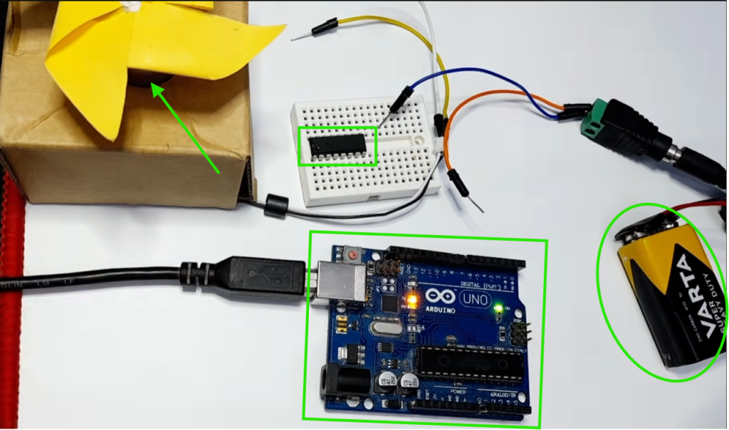
I highly recommend getting a complete starter kit that includes everything you need to create a wide range of projects.
L293D Pinout
The L293D has 16 pins. Let’s break them down :

| Pin | Name | Description |
|---|---|---|
| 1 | Enable 1 | PWM Speed Control |
| 2 | Input 1 | Motor A Direction |
| 3 | Output 1 | Motor A |
| 4 | GND | Ground |
| 5 | GND | Ground |
| 6 | Output 2 | Motor A |
| 7 | Input 2 | Motor A Direction |
| 8 | Motor Supply | External Motor Voltage |
| 9 | Enable 2 | PWM Speed Control |
| 10 | Input 3 | Motor B Direction |
| 11 | Output 3 | Motor B |
| 12 | GND | Ground |
| 13 | GND | Ground |
| 14 | Output 4 | Motor B |
| 15 | Input 4 | Motor B Direction |
| 16 | Logic Supply | 5V |
Wiring Diagram
Let’s wire everything up. I’ll use this pin mapping :
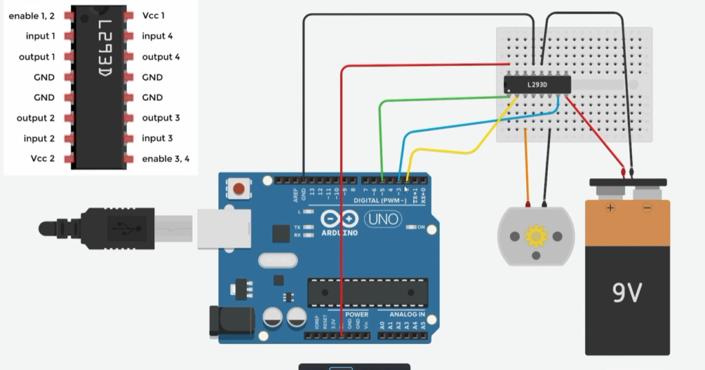
| L293D Pin | Arduino Pin |
|---|---|
| Enable 1-2 (pin 1) | D5 (PWM) |
| Input 1 (pin 2) | D3 |
| Input 2 (pin 7) | D2 |
| Enable 3-4 (pin 9) | Not used |
| Input 3 (pin 10) | Not used |
| Input 4 (pin 15) | Not used |
| VCC 1 (pin 16) | Arduino 5V |
| VCC 2 (pin 8) | External battery + |
| GND (pins 4, 5, 12, 13) | Arduino GND and battery – |
Step-by-Step Wiring
- Power Logic → Connect L293D pin 16 to Arduino 5V
- Power Motors → Connect L293D pin 8 to the external battery positive
- Common Ground → Connect L293D pins 4, 5, 12, 13 to Arduino GND AND battery negative (this is critical!)
- Motor A → Connect your first motor to pins 3 and 6
- Motor B → You could connect your second motor to pins 11 and 14 (For me, it is not used)
- Control Pins → Connect the inputs and enable pins to Arduino as shown above
⚠️ Critical Tip: The ground of your external battery MUST be connected to the Arduino’s ground. Without a common ground, the control signals won’t work .
How the L293D Controls Motors
Direction Control
The direction pins (Input 1 & 2 for Motor A, Input 3 & 4 for Motor B) control which way the motor spins. Here’s the logic :
| Input 1/3 | Input 2/4 | Motor Behavior |
|---|---|---|
| LOW | LOW | Stop/Brake |
| HIGH | LOW | Forward |
| LOW | HIGH | Backward |
| HIGH | HIGH | Stop/Brake |
Speed Control
The Enable pins are connected to PWM-capable Arduino pins. Using analogWrite(), you can send values from 0 to 255 :
0→ Motor off255→ Full speed- Values in between → Variable speed
Arduino Code
Here’s a complete sketch that demonstrates independent control of one DC motor:
// L293D Motor Control
// Motor A
const int ENA = 5;   // PWM pin for speed
const int IN1 = 3;
const int IN2 = 2;

// Motor B (Not used in this guide)
const int ENB = 9;  // PWM pin for speed
const int IN3 = 8;
const int IN4 = 7;

void setup() {
  // Set all pins as outputs
  pinMode(ENA, OUTPUT);
  pinMode(IN1, OUTPUT);
  pinMode(IN2, OUTPUT);
  pinMode(ENB, OUTPUT);
  pinMode(IN3, OUTPUT);
  pinMode(IN4, OUTPUT);

  // Start with motors stopped
  stopMotors();
}

void loop() {
  // Motor A forward at full speed
  // Motor B forward at half speed
  setMotorA('F', 255);
  setMotorB('F', 128);
  delay(3000);

  // Both motors backward
  setMotorA('B', 255);
  setMotorB('B', 255);
  delay(3000);

  // Turn: Motor A forward, Motor B backward
  setMotorA('F', 200);
  setMotorB('B', 200);
  delay(2000);

  // Stop
  stopMotors();
  delay(2000);
}

/**
 * Control Motor A
 * direction: 'F'=forward, 'B'=backward, 'S'=stop
 * speed: 0-255
 */
void setMotorA(char direction, int speed) {
  analogWrite(ENA, speed);
  switch(direction) {
    case 'F':
      digitalWrite(IN1, HIGH);
      digitalWrite(IN2, LOW);
      break;
    case 'B':
      digitalWrite(IN1, LOW);
      digitalWrite(IN2, HIGH);
      break;
    default: // Stop
      digitalWrite(IN1, LOW);
      digitalWrite(IN2, LOW);
  }
}

/**
 * Control Motor B
 * direction: 'F'=forward, 'B'=backward, 'S'=stop
 * speed: 0-255
 */
void setMotorB(char direction, int speed) {
  analogWrite(ENB, speed);
  switch(direction) {
    case 'F':
      digitalWrite(IN3, HIGH);
      digitalWrite(IN4, LOW);
      break;
    case 'B':
      digitalWrite(IN3, LOW);
      digitalWrite(IN4, HIGH);
      break;
    default: // Stop
      digitalWrite(IN3, LOW);
      digitalWrite(IN4, LOW);
  }
}

void stopMotors() {
  digitalWrite(IN1, LOW);
  digitalWrite(IN2, LOW);
  digitalWrite(IN3, LOW);
  digitalWrite(IN4, LOW);
  analogWrite(ENA, 0);
  analogWrite(ENB, 0);
}
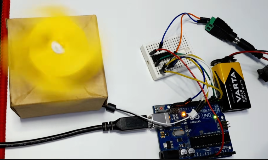
Code Explanation
Defining the Motor Pins
The first section assigns Arduino pins to the L293D inputs.
// Motor A
const int ENA = 5;
const int IN1 = 3;
const int IN2 = 2;

// Motor B
const int ENB = 9;
const int IN3 = 8;
const int IN4 = 7;
Notice that ENA and ENB are connected to PWM pins. This allows the Arduino to vary the motor speed using the analogWrite() function.
The setup() Function
void setup() {

  pinMode(ENA, OUTPUT);
  pinMode(IN1, OUTPUT);
  pinMode(IN2, OUTPUT);

  pinMode(ENB, OUTPUT);
  pinMode(IN3, OUTPUT);
  pinMode(IN4, OUTPUT);

  stopMotors();
}
The setup() function runs only once after the Arduino is powered on or reset.
Its responsibilities are:
- Configure every control pin as an output.
- Stop both motors before the program begins.
Starting with the motors stopped is a good programming practice because it prevents unexpected movement when the board powers up.
Move Both Motors Forward
setMotorA('F', 255);
setMotorB('F', 128);

delay(3000);
Motor A runs:
- Forward
- Full speed
Motor B runs:
- Forward
- Half speed
This demonstrates that each motor can operate at a different speed independently.
Reverse Both Motors
setMotorA('B', 255);
setMotorB('B', 255);

delay(3000);
Now both motors rotate in the opposite direction at maximum speed.
Stop the Motors
stopMotors();
delay(2000);
Finally, both motors stop before the sequence repeats.
Speed Control
analogWrite(ENA, speed);The analogWrite() function generates a PWM signal.
Higher values produce faster motor rotation.
Examples:
analogWrite(ENA, 50);Very slow.
analogWrite(ENA, 120);Medium speed.
analogWrite(ENA, 255);Maximum speed.
Potentiometer Speed Control
Want to control motor speed with a knob? This variation maps an analog input to PWM :
// Motor A
const int ENA = 5;   // PWM pin for speed
const int IN1 = 3;
const int IN2 = 2;

int potPin = A0;

void setup() {
  pinMode(ENA, OUTPUT);
  pinMode(IN1, OUTPUT);
  pinMode(IN2, OUTPUT);
  pinMode(potPin, INPUT);

  // Set direction: forward
  digitalWrite(IN1, HIGH);
  digitalWrite(IN2, LOW);
}

void loop() {
  int potValue = analogRead(potPin);
  int motorSpeed = map(potValue, 0, 1023, 0, 255);
  analogWrite(ENA, motorSpeed);
  delay(50);
}
Troubleshooting Common Issues
Motors Don’t Move
- Check the ground: Arduino GND and battery GND must be connected
- Check power: Pin 16 needs 5V, pin 8 needs 4.5V–36V
- Check enable pins: Both must be connected to PWM pins and set with
analogWrite()
Motors Only Run One Direction
- Swap the IN pins in your code or check wiring
- Ensure you’re setting pins opposite (one HIGH, one LOW)
IC Gets Very Hot
- Your motors may be drawing more than 600mA—switch to L298N for higher current
- Add a heatsink to the L293D
- Check for short circuits in your wiring
No Speed Control
- Make sure the enable pins are on PWM-capable pins (marked with ~ on Arduino)
- Use
analogWrite()notdigitalWrite()for speed
Summary: L293D at a Glance
The L293D Motor Driver IC is an excellent choice for learning the basics of motor control with Arduino.
It provides an easy way to control the speed and direction of two DC motors while introducing the concepts of H-Bridge operation and PWM.
Although it is best suited for smaller motors, it remains a valuable component for educational projects, compact robots, and DIY electronics. Once you master the L293D, transitioning to more powerful drivers such as the L298N or TB6612FNG becomes much easier.