How to Control 2 DC Motors with Arduino & the L298N Motor Driver: Complete Guide

The L298N Motor Driver Module is one of the most popular motor drivers used in Arduino projects. It allows an Arduino to control the speed and direction of two DC motors independently, making it ideal for robotics, RC vehicles, conveyor systems, automated doors, and many other DIY electronics projects.
So, we will learn everything you need to know about connecting the L298N, controlling 2 DC motors, adjusting motor speed with PWM, and understanding how the driver works internally.
What is the L298N Motor Driver?
The L298N is a dual H-Bridge motor driver capable of driving:
- Two DC motors independently
- One bipolar stepper motor
- Motors from 5V to 35V
- Up to 2A peak per channel (about 1A continuous without additional cooling)

Because Arduino pins cannot provide enough current to drive motors directly, the L298N acts as an interface between the Arduino and the motors.
Think of an H-bridge as an electronic switch that allows you to reverse the polarity of the voltage applied to your motor, which is how you change its direction
L298N Pinout
Before we start wiring, let’s understand the pins on the L298N module :

| Pin Name | Function |
|---|---|
| 12V (VCC) | Main motor power supply (5V–35V) |
| GND | Common ground for power and logic |
| 5V | Logic power (input/output via onboard regulator) |
| ENA | Enable and speed control for Motor A (PWM) |
| IN1, IN2 | Direction control for Motor A |
| ENB | Enable and speed control for Motor B (PWM) |
| IN3, IN4 | Direction control for Motor B |
| OUT1, OUT2 | Terminal connects to Motor A |
| OUT3, OUT4 | Terminal connects to Motor B |
How Does an H-Bridge Work?
An H-Bridge reverses the polarity applied to a motor: changing polarity reverses the motor’s rotation.
For example:
| IN1 | IN2 | Motor |
|---|---|---|
| LOW | LOW | Stop |
| HIGH | LOW | Forward |
| LOW | HIGH | Reverse |
| HIGH | HIGH | Brake |
The same applies to Motor B, which uses IN3 and IN4.
Components You’ll Need
Here’s the shopping list for this project:
- 1 × Arduino Uno (or compatible board)
- 1 × L298N Motor Driver Module
- 2 × DC Motors (any voltage within the driver’s range)
- 1 × External Power Supply (battery pack or DC adapter, 5V–35V)
- Jumper wires (male-to-female for easy connections)
- Optional: Power switch, chassis, wheels
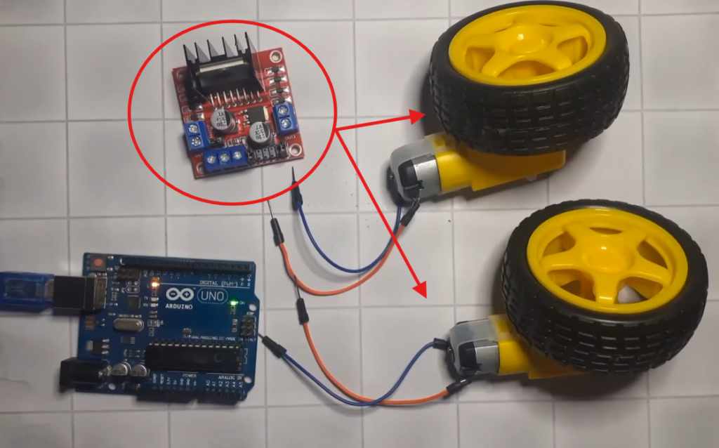
I highly recommend getting a complete starter kit that includes everything you need to create a wide range of projects.
Circuit Diagram
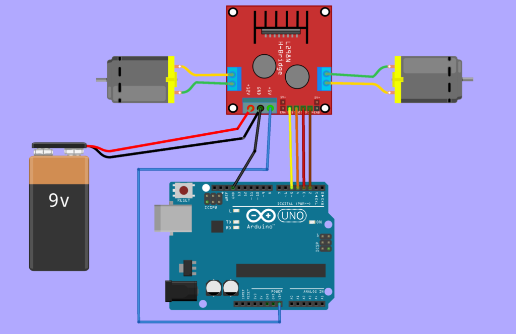
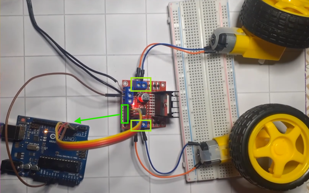
Driver Connections:
| L298N | Arduino |
|---|---|
| ENA | 5v |
| IN1 | D5 |
| IN2 | D4 |
| IN3 | D3 |
| IN4 | D2 |
| ENB | 5v |
| GND | GND |
Motor Connections:
Motor A (Left Motor)
- OUT1
- OUT2
Motor B (Right Motor)
- OUT3
- OUT4
Power Connections:
External Battery
Battery Positive → 12V
Battery Negative → GND
Arduino GND → L298N GND
Important: Always connect the Arduino ground to the motor driver’s ground.
Arduino Code
// Motor A (Left Motor)
#define IN1 4
#define IN2 5

// Motor B (Right Motor)
#define IN3 2
#define IN4 3

void setup()
{
  pinMode(IN1, OUTPUT);
  pinMode(IN2, OUTPUT);

  pinMode(IN3, OUTPUT);
  pinMode(IN4, OUTPUT);
}

void loop()
{
  // Forward
  digitalWrite(IN1, HIGH);
  digitalWrite(IN2, LOW);

  digitalWrite(IN3, HIGH);
  digitalWrite(IN4, LOW);

  delay(5000);

  // Stop
  digitalWrite(IN1, LOW);
  digitalWrite(IN2, LOW);

  digitalWrite(IN3, LOW);
  digitalWrite(IN4, LOW);

  delay(1000);

  // Reverse
  digitalWrite(IN1, LOW);
  digitalWrite(IN2, HIGH);

  digitalWrite(IN3, LOW);
  digitalWrite(IN4, HIGH);

  delay(5000);

  // Stop
  digitalWrite(IN1, LOW);
  digitalWrite(IN2, LOW);

  digitalWrite(IN3, LOW);
  digitalWrite(IN4, LOW);

  delay(1000);
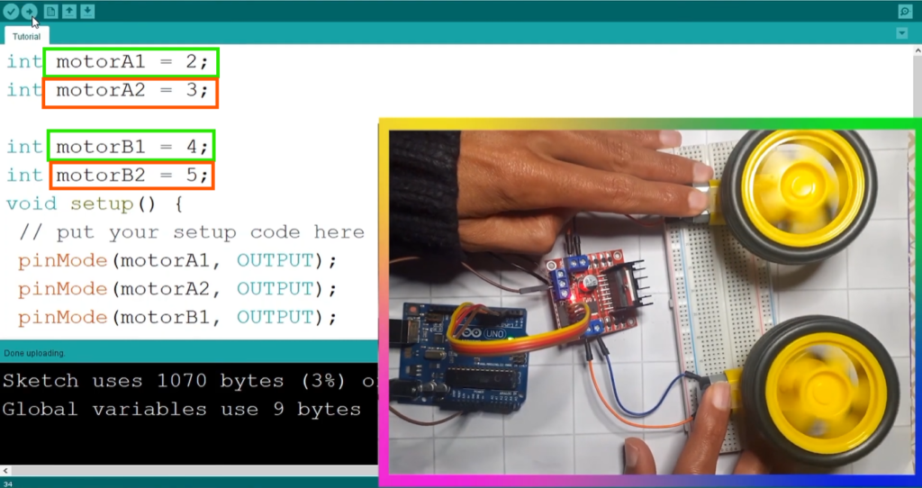
}
Using Potentiometer for Speed Control
Speed control uses Pulse Width Modulation (PWM) on the ENA and ENB pins. The analogWrite() function sends a signal from 0 to 255, where :
0= motor off255= full speed- Values in between = variable speed
Here’s a variation that uses a potentiometer to control motor speed :
// Motor A (Left Motor)
#define ENA 9
#define IN1 4
#define IN2 5

int potPin = A0;

void setup() {
  pinMode(ENA, OUTPUT);
  pinMode(IN1, OUTPUT);
  pinMode(IN2, OUTPUT);

  digitalWrite(IN1, HIGH);
  digitalWrite(IN2, LOW);
}

void loop() {
  int potValue = analogRead(potPin);
  int motorSpeed = map(potValue, 0, 1023, 0, 255);
  analogWrite(ENA, motorSpeed);
}
The potentiometer reads values from 0-1023, mapped to the PWM range of 0-255 for smooth speed control.
Troubleshooting Common Issues
Motor Doesn’t Move
- Check power: Ensure your external battery is charged and connected to VCC and GND.
- Check the jumper: If using >12V, the 5V jumper must be removed and a separate 5V provided.
- Ground connection: Arduino GND and L298N GND must be connected!
- Verify pins: Double-check that control pins match your code.
Motor Spins But No Speed Control
- Ensure ENA/ENB are connected to PWM-capable pins (usually marked with
~). - Check that you’re using
analogWrite()and notdigitalWrite()for speed.
Motors Run Slowly
- Your external battery voltage might be too low for the motors.
- Check the PWM value—are you using the full 0-255 range?
Motors Only Spin One Direction
- Verify the IN pin logic—try swapping HIGH and LOW in the code.
- Check for damaged wiring or loose connections.
Conclusion
The L298N Motor Driver is an excellent starting point for learning motor control with Arduino. By using its dual H-bridge design, you can independently control the speed and direction of two DC motors, making it a great choice for robotics and automation projects. Once you’re comfortable with the basics, you can expand this setup by adding Bluetooth, Wi-Fi, ultrasonic sensors, or joysticks to build more advanced and interactive robotic systems.