Bluetooth Control App with MIT App Inventor – DIY Project
Have you ever wanted to control lights, fans, or any electronic device directly from your smartphone? With the power of MIT App Inventor and a simple microcontroller like the ESP32 or Arduino, you can build your own custom Internet of Things (IoT) application in just a few minutes.
The best part? You don’t need to be a professional programmer to do it.
I’ll walk you through creating a Bluetooth LED Control App. Whether you have an ESP32 (which uses Bluetooth Low Energy) or a classic Arduino Uno with an HC-05 module (which uses Classic Bluetooth), I’ve got you covered.
Why ESP32 is Better?
Whether you use an ESP32 or an Arduino Uno with an HC-05 module, we will build the same Android application with MIT App Inventor’s intuitive drag-and-drop interface.
The ESP32 is my go-to choice for this project, and here’s why:
- Built-in Bluetooth: No need for external modules like HC-05 – everything is integrated
- Dual-core processor: Handles complex tasks with ease
- Wi-Fi capability: You can easily upgrade this project to IoT later
- Cost-effective: Amazing value for the features you get
🧰 What You’ll Need?
Hardware Requirements:
- ESP32 Development Board (e.g., ESP32 DevKit, NodeMCU-32S, or ESP32-C3).
- Standard 5mm LED (any color)
- 220Ω or 330Ω resistor
- Breadboard and jumper wires
- Android smartphone for testing
If you want to use an Arduino board with an HC module:
- Arduino Uno (or similar).
- Bluetooth Module: HC-05 or HC-06 module.
Software Requirements:
- Arduino IDE Download the latest version from arduino.cc.
- A Google Account to log in to MIT App Inventor.
Step 1: Setting Up Your ESP32
If you haven’t used ESP32 with Arduino IDE before, follow these quick setup steps:
- Open Arduino IDE
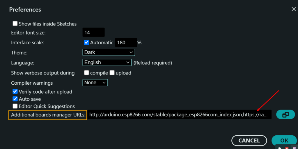
- Go to File > Preferences
- In the “Additional Board Manager URLs” field, add: https://raw.githubusercontent.com/espressif/arduino-esp32/gh-pages/package_esp32_index.json
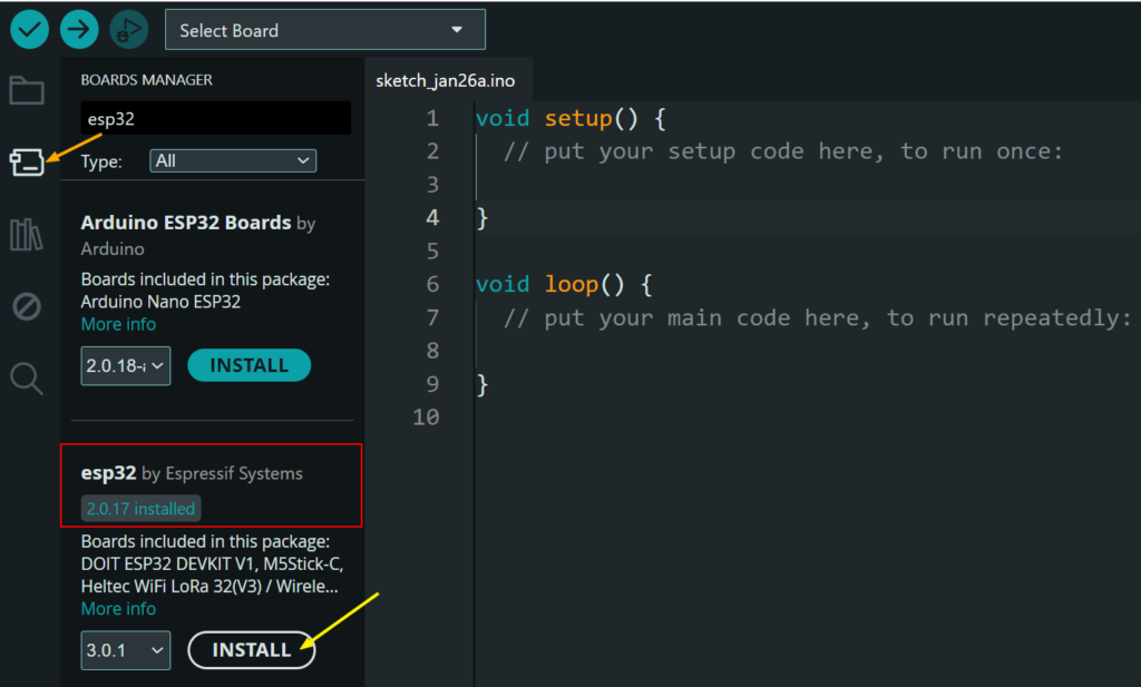
- Go to Tools > Board > Boards Manager
- Search for “ESP32” and install the ESP32 platform by Espressif Systems
- Select your ESP32 board from Tools > Board > ESP32 Device
Step 2: Circuit Diagram (ESP32/Arduino)
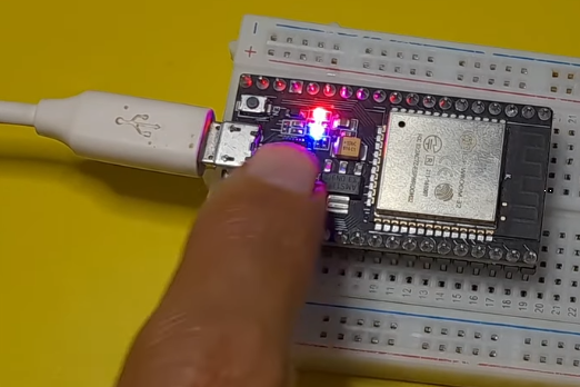
Most ESP32 development boards come with a built-in LED connected to GPIO 2. This is the same LED that blinks when you run the classic “Blink” example.
If you want to use an external LED, follow this circuit:
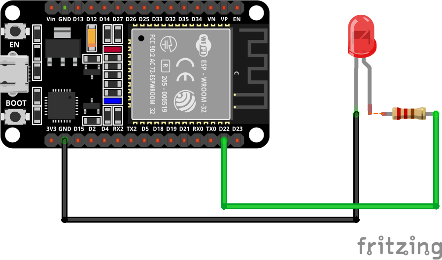
- Connect the anode (long leg) of the LED to one end of the 220Ω resistor
- Connect the other end of the resistor to any GPIO pin (Digital pin 22) on the ESP32
- Connect the cathode (short leg) to the GND of the esp32
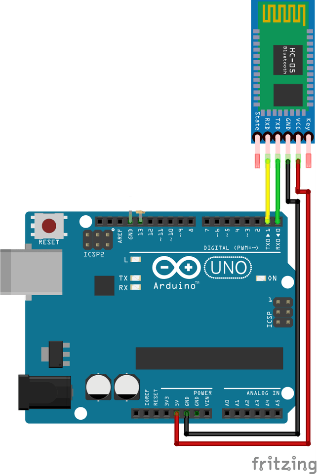
(Arduino + HC-05 Module Wiring):
The HC-05 is a popular Bluetooth module that adds wireless Bluetooth communication to Arduino.
- HC-05 TX → Arduino Pin 0 (RX)
- HC-05 RX → Arduino Pin 1 (TX)
- HC-05 VCC → Arduino 5V
- HC-05 GND → Arduino GND
You could control its built-in LED, which is connected to the PIN 13
Step 3: Complete Code
Now let’s upload the code that makes your ESP32 a BLE server. This code creates a Bluetooth device that advertises itself and listens for commands.
Open Arduino IDE, paste the following code, select your ESP32 board and port, then hit upload:
//#include <SoftwareSerial.h>
#include "BluetoothSerial.h"

const int ledPin = 2;

//SoftwareSerial MyBlue(0, 1);  // RX | TX
BluetoothSerial MyBlue;
char cmd;

void setup() {

  pinMode(ledPin, OUTPUT);

  //MyBlue.begin(9600);
  MyBlue.begin("ESP32-LED-Controller");
}

void loop() {

  // Bluetooth Control
  if (MyBlue.available()) {
    cmd = MyBlue.read();

    if (cmd == '1') {
      digitalWrite(ledPin, HIGH);
    } else if (cmd == '0') {
      digitalWrite(ledPin, LOW);
    }
  }

  delay(10);
}
Your ESP32 is now broadcasting! Keep it powered via USB.
For those who have Arduino boards and HC-05 modules, here’s a quick alternative:
#include <SoftwareSerial.h>

SoftwareSerial BT(0, 1); // RX, TX
const int ledPin = 13;
char command;

void setup() {
  Serial.begin(9600);
  BT.begin(9600);
  pinMode(ledPin, OUTPUT);
  Serial.println("Arduino Bluetooth Ready");
}

void loop() {
  if (BT.available()) {
    command = BT.read();
    if (command == '1') {
      digitalWrite(ledPin, HIGH);
      Serial.println("LED ON");
    }
    else if (command == '0') {
      digitalWrite(ledPin, LOW);
      Serial.println("LED OFF");
    }
  }
}
Step 4: Create the App with MIT
Now for the exciting part – creating your own Android app without writing a single line of complex code!
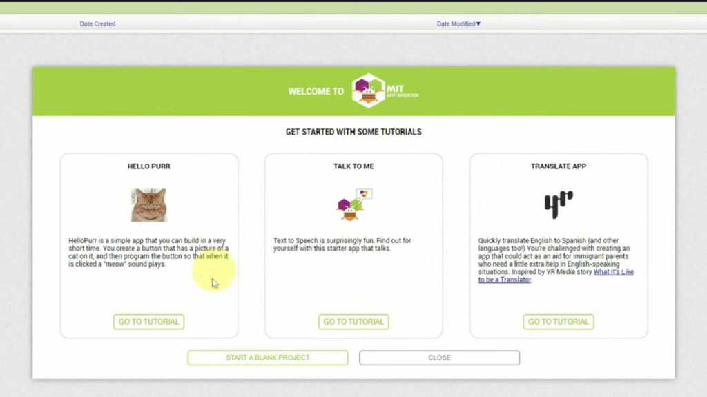
Create a New Project:
- Go to MIT App Inventor
- Click “Start a new project”
- Name it ESP32_LED_Controller
Design the User Interface:
Let’s create a clean, professional-looking interface by using some components:
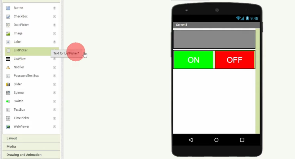
Device List (Picker)
- Drag a ListPicker component
- Change Text to
Devices List - Set Width to “Fill parent”
Connection Status Label
- Drag a Label
- Set Text to “Not Connected”
- Set FontSize to 16
- TextColor to white
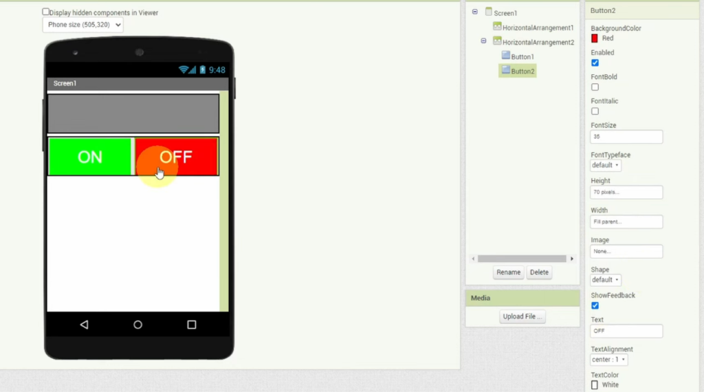
ON Button/OFF Button
- Drag a HorizontalArrangement
- Set Width to “Fill parent”
- Set AlignHorizontal to “Center”
- Inside the arrangement, add 2 Buttons
- Set Text to “ON”/ “OFF” for each Button
- Set BackgroundColor to green (On Button) / BackgroundColor to red (Off Button)
- Set FontSize to 24 for both
- Set Width to 150 pixels
- Set Height to 80 pixels
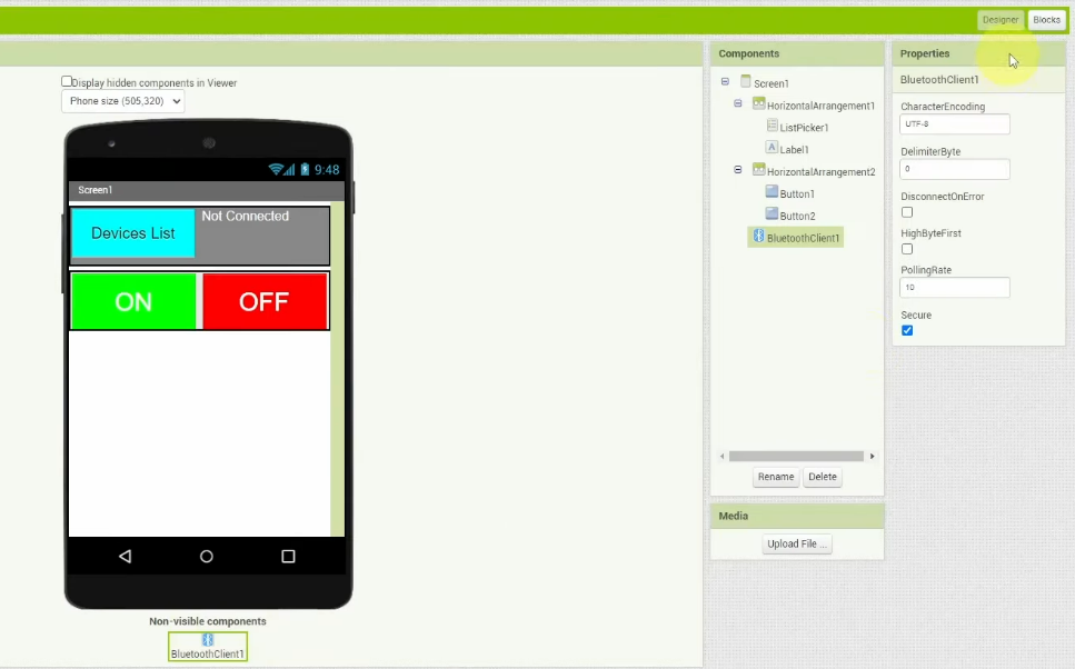
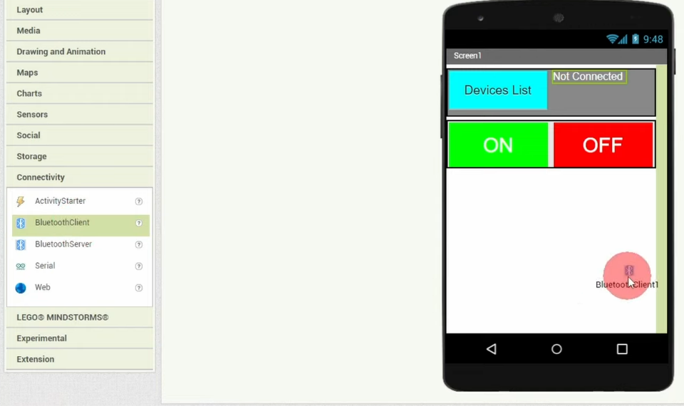
BluetoothLE Component (non-visible)
- From “Connectivity” in the palette, drag “BluetoothClient”
- It will appear at the bottom under “Non-visible components”
Adding the Logic (Blocks):
Now switch to the Blocks view.
This is where we’ll program the behavior using visual blocks.
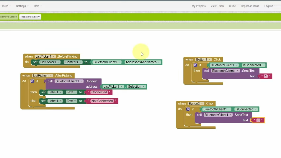
Block 1 (Before Picking): Scans for Devices
When the user clicks the “ListPicker” button, we start scanning for bluetooth devices and we display the founded devices during scanning:
Block 2 (After Picking): Connect to Selected Device
When the user selects a device from the list:
- If connection is successful: We display “Connected” using Label1
- But when connection is lost: We display “Not Connected” using Label1
Block 3/4(Button1, Button2): Send Commands
When ON button is clicked: we send the text “1”
When OFF button is clicked: we send the text “0”
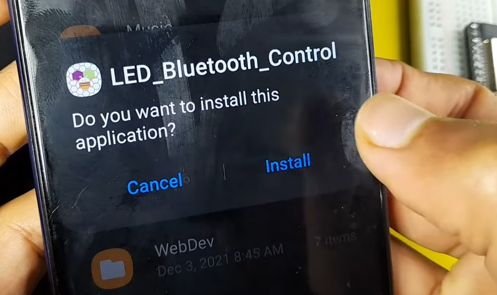
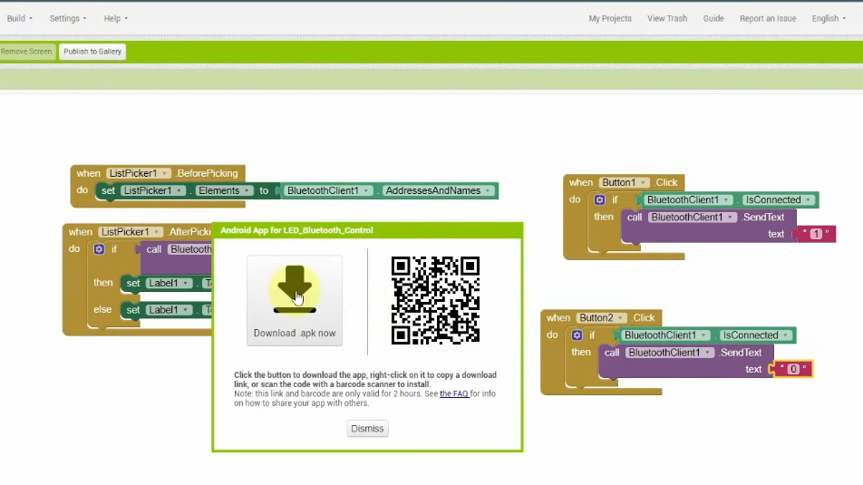
Build and Install:
Now, head over to Build and Download APK file then install it using your smartphone.
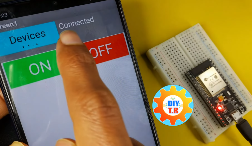
Step 5: Testing Complete System
Now for the moment of truth!
- Ensure your ESP32 is powered and running the Code (check Serial Monitor)
- On your phone, Enable Bluetooth and Pair it with the ESP32 or Arduino HC Module
- Open your app, and Click “Devices” – you should see “ESP32-LED-Controller” appear
- Select your device from the list
- Wait for connection – the status should be “Connected“
- Press the ON button – the LED on GPIO 2 should light up!
- Press the OFF button – the LED should turn off
Common Issues (troubleshooting)
ESP32 Not Found in Scan
- Make sure the ESP32 is powered and the code is running (check Serial Monitor)
- Try restarting the ESP32 by pressing the EN button
- On your phone, make sure Bluetooth is enabled
- Android sometimes requires location permission for Bluetooth scanning – grant it
Commands Not Working
- Check the LED connection (polarity matters!)
- Make sure GPIO 2 is correct for your board (some ESP32 variants use different pins)
- Add debug prints in the ESP32 code to verify it’s receiving data
Conclusion
Congratulations! You’ve successfully built a complete Bluetooth-controlled LED system using the ESP32 as your main controller.
This project is just the beginning. The ESP32’s built-in BLE capability makes it perfect for countless IoT and home automation projects. With the app development skills you’ve learned in MIT App Inventor, you can now create custom controllers for anything you can imagine.
What will you control next? A robotic car? A smart home system? A wearable device? The possibilities are endless!