Complete Guide to GC9A01 Round Display with ESP32 & Arduino
The GC9A01 round TFT display is not just another screen. Unlike standard rectangular screens, a circular LCD adds a touch of style and sophistication — it’s a powerful way to create modern, smartwatch-style user interfaces in your electronics projects.
In this guide, I’ll walk you through everything you need to know: from wiring it up and configuring the tricky library settings to writing your first sketch and exploring advanced project ideas.
📌 What is the GC9A01 Display?
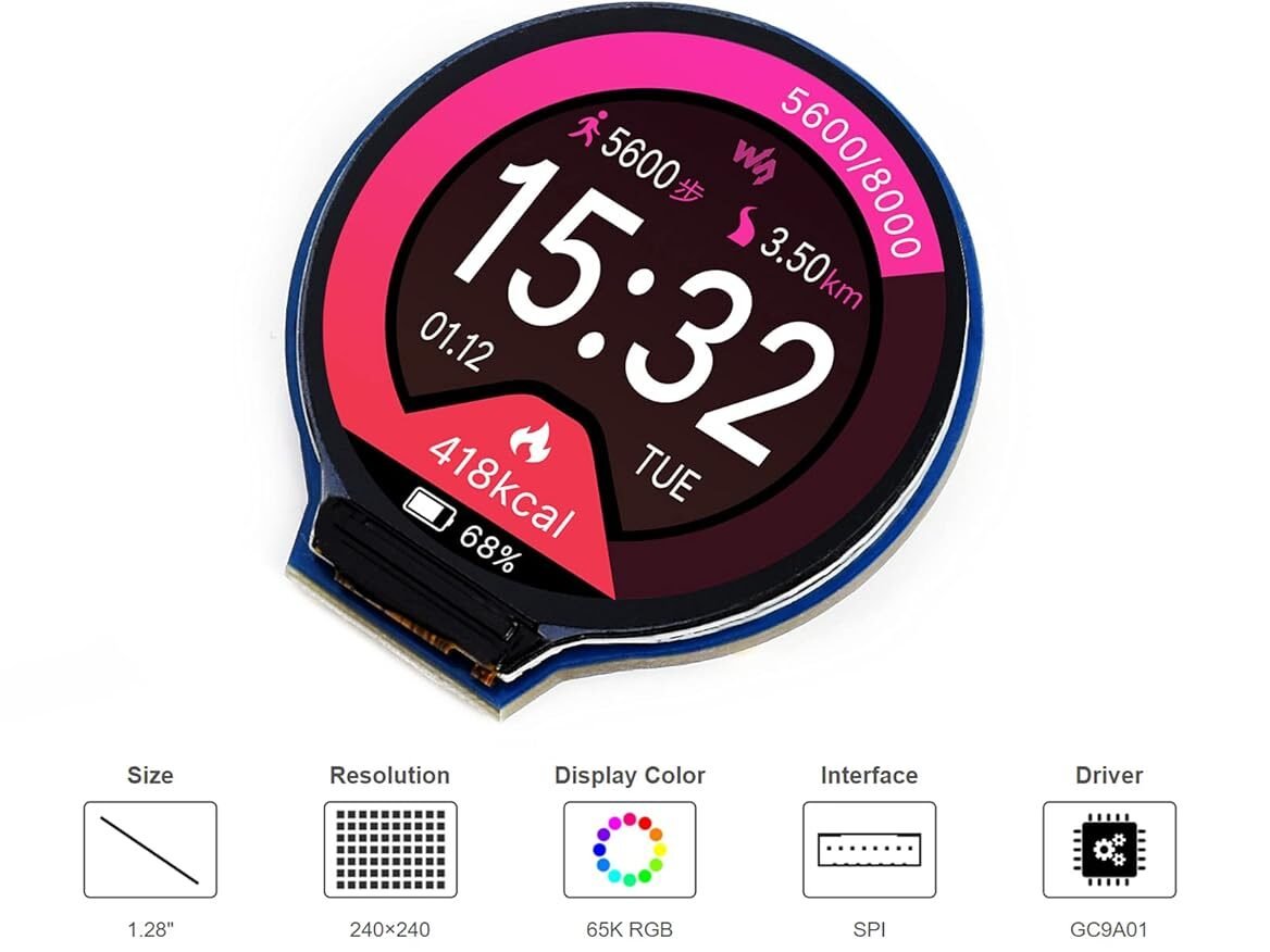
The GC9A01 is a 1.28-inch circular TFT LCD that communicates using the SPI protocol. It offers:
- 🟢 240×240 resolution
- 🟢 Full-color display (RGB)
- 🟢 Smooth graphics rendering
- 🟢 Compact round design
🧰 Components Required
Here is the hardware list for this Guide:
- 1x ESP32 Development Board (ESP32-S variants work, but standard ESP32 Dev Kit C is most common).
- 1x GC9A01 Round LCD Display (1.28″ 240×240 pixels).
- 1x Breadboard & Jumper Wires (Male-to-Female are best for display modules).
- USB Cable (for power and programming).
- Software:
- Arduino IDE Or VSCode
- ESP32 Board Support Package
Note: If you haven’t set up your IDE with ESP32 support yet, please follow my previous ESP32 Guide
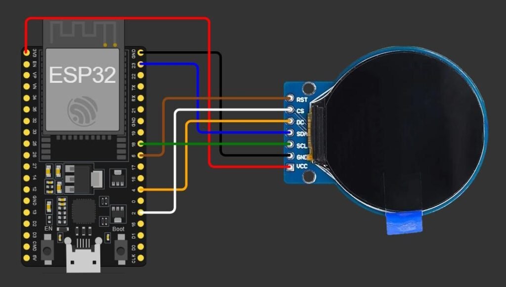
🔌 Circuit Connections (ESP32)
⚠️ Voltage Level:
- GC9A01 is usually 3.3V logic
- Some modules include regulators → can accept 5V
👉 If unsure: Use 3.3V (safe option)
⚡ GC9A01 Pinout:
| Pin | Description |
|---|---|
| VCC | Power (3.3V recommended) |
| GND | Ground |
| SCL (SCLK) or DIN | SPI Clock |
| SDA (CLK) | SPI Data (MOSI) |
| CS | Chip Select |
| DC | Data/Command |
| RST | Reset |
| BLK | Backlight |
Pro Tip: If your display has a “BL” or “LED” pin, connecting it directly to 3.3V is fine for testing. If you want to turn the backlight off in software (to save battery for a watch), connect this to a PWM-capable pin like GPIO 21.
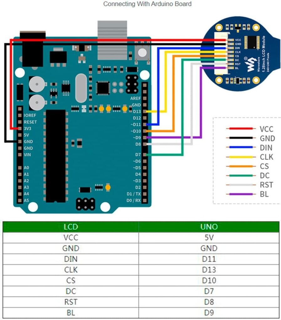
🔌 Circuit Connections (Arduino)
⚙️ Configuring TFT_eSPI Library
The TFT_eSPI library by Bodmer is the gold standard for these displays, but it doesn’t use “magic” auto-configuration. You must tell it exactly what screen, board, and pins you are using.
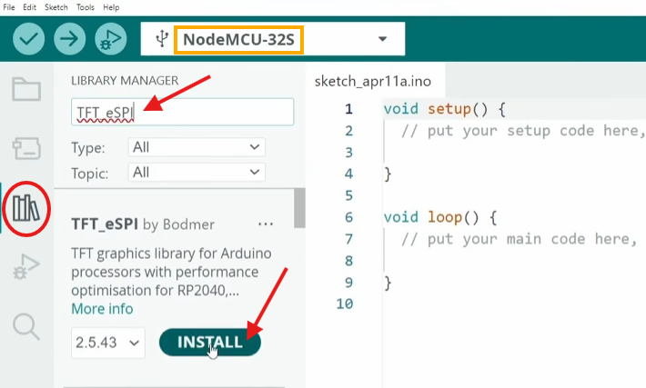
1. Installation:
Open your Arduino IDE. Go to Sketch -> Include Library -> Manage Libraries. Search for “TFT_eSPI” and install it by Bodmer.
2. Configuration (“User_Setup_Select.h” File)
This is where most people get stuck. You cannot just run the code yet; you need to edit the library settings.
- Navigate to your Arduino libraries folder (usually
Documents/Arduino/libraries). - Open the
TFT_eSPIfolder. - Open the
User_Setup_Select.hfile in a text editor. - Comment out the generic setup lines and include the GC9A01 specific setup.
Find the section #include <User_Setups/...> and modify it to look like this:
// User_Setup_Select.h

// Comment out the generic default
//#include <User_Setup.h>           // Default setup is root library folder

// Enable the GC9A01 Round display setup file
#include <User_Setups/Setup200_GC9A01.h> // Setup file for ESP32 and GC9A01 driver
3. Custom Pin Mapping (Recommended)
While Setup200_GC9A01.h Works for some boards, it’s safer to manually define your pins, which prevents conflicts and ensures that our specific wiring works.
So, open up the User_Setups Folder and edit the “Setup200_GC9A01.h” file, paste the configuration below. This matches the wiring diagram we used.
// See SetupX_Template.h for all options available
#define USER_SETUP_ID 200

#define GC9A01_DRIVER

// For ESP32 Dev board (only tested with GC9A01 display)
// The hardware SPI can be mapped to any pins

#define TFT_MOSI 23 // In some display driver board, it might be written as "SDA" and so on.
#define TFT_SCLK 18
#define TFT_CS   2  // Chip select control pin
#define TFT_DC   4  // Data Command control pin
#define TFT_RST  5  // Reset pin (could connect to Arduino RESET pin)
#define TFT_BL   21  // LED back-light

#define LOAD_GLCD   // Font 1. Original Adafruit 8 pixel font needs ~1820 bytes in FLASH
#define LOAD_FONT2  // Font 2. Small 16 pixel high font, needs ~3534 bytes in FLASH, 96 characters
#define LOAD_FONT4  // Font 4. Medium 26 pixel high font, needs ~5848 bytes in FLASH, 96 characters
#define LOAD_FONT6  // Font 6. Large 48 pixel font, needs ~2666 bytes in FLASH, only characters 1234567890:-.apm
#define LOAD_FONT7  // Font 7. 7 segment 48 pixel font, needs ~2438 bytes in FLASH, only characters 1234567890:.
#define LOAD_FONT8  // Font 8. Large 75 pixel font needs ~3256 bytes in FLASH, only characters 1234567890:-.
#define LOAD_GFXFF  // FreeFonts. Include access to the 48 Adafruit_GFX free fonts FF1 to FF48 and custom fonts

#define SMOOTH_FONT

//#define SPI_FREQUENCY  80000000
#define SPI_FREQUENCY  27000000

// Optional reduced SPI frequency for reading TFT
#define SPI_READ_FREQUENCY  5000000
Save the files. You have now successfully installed the right driver.
💻 Your First Sketch (“Hello World”)
To verify everything works, let’s upload a simple test. This sketch will fill the round screen with colors and print text.
#include <TFT_eSPI.h> // Include the library

TFT_eSPI tft = TFT_eSPI(); // Create an object

void setup() {
  Serial.begin(115200);
  tft.init();            // Initialize the screen
  tft.setRotation(0);    // 0 = portrait, 1,2,3 are other rotations
  tft.fillScreen(TFT_BLACK); // Clear screen to black

  // Let's draw a circle in the center!
  tft.fillCircle(120, 120, 100, TFT_BLUE); // 240x240 screen, center is 120,120

  // Set up text properties
  tft.setTextColor(TFT_WHITE, TFT_BLUE); // White text, Blue background
  tft.setTextSize(2);                   // Font size multiplier
  tft.setCursor(55, 115);               // Position (roughly center)
  tft.println("Hello World!");

  Serial.println("Screen initialized successfully");
}

void loop() {
  // Nothing here for now
}
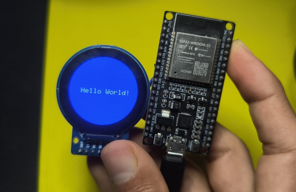
Upload and Observe: You should see a blue circle with “Hello World!” in the center.
If the screen stays white or black:
- Double-check wiring: A loose SDA or SCL wire
- Check the config: Ensure you saved
User_Setup.hcorrectly. - Power: Make sure the display’s VCC is on 3.3V, not 5V.
🔥 Level Up – Other Project Ideas
Now that the basics are working, we can take a look at the examples of this TFT_eSPI library:
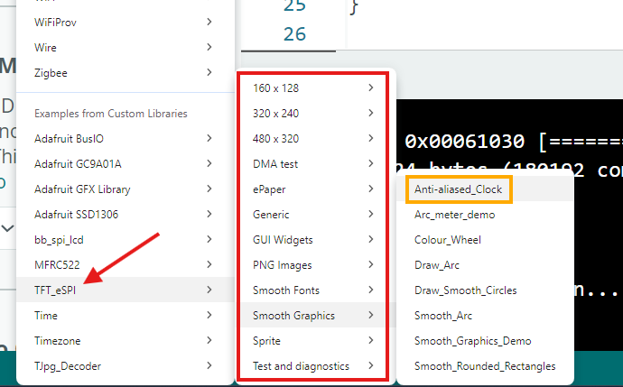
Here are some popular directions you can take with this hardware, along with the specific code concepts they use.
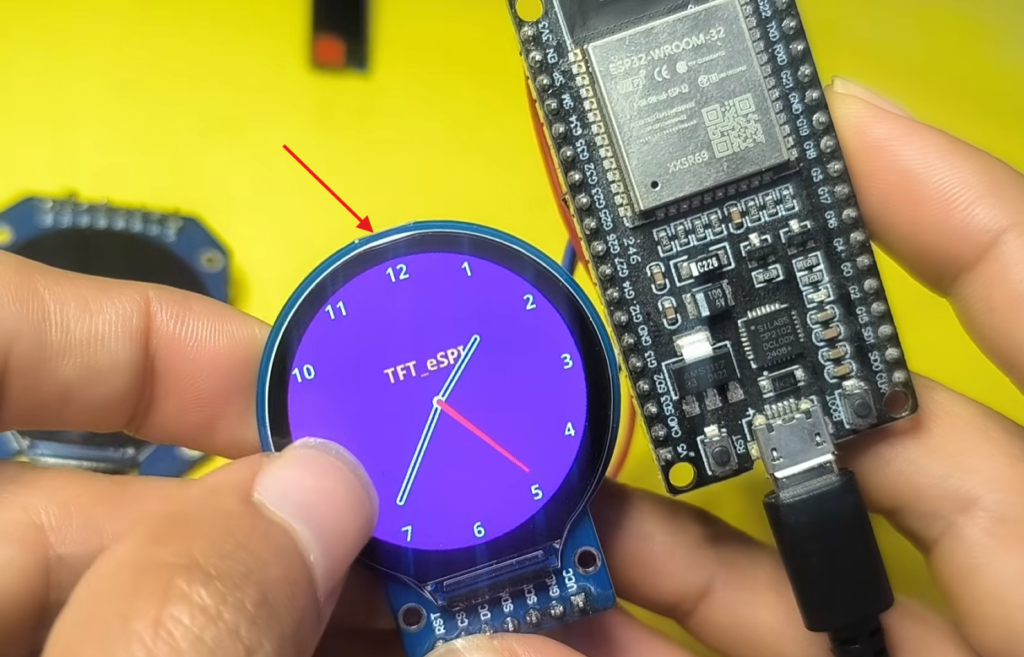
1. The Analog Clock (WiFi + NTP)
The classic round display project. Using the ESP32’s WiFi, you can fetch the exact time from the internet (NTP – Network Time Protocol) and draw analog hands.
- How it works: The
configTime()function syncs the time. You calculate the X/Y coordinates of the clock hands usingsinandcos(trigonometry) based on the current hour/minute/second. - Key Code Concept:
tft.drawLine()for the hands, and crucially, drawing the hands in black first (to erase them) and redrawing them in color at the new position to create smooth motion without clearing the whole screen.
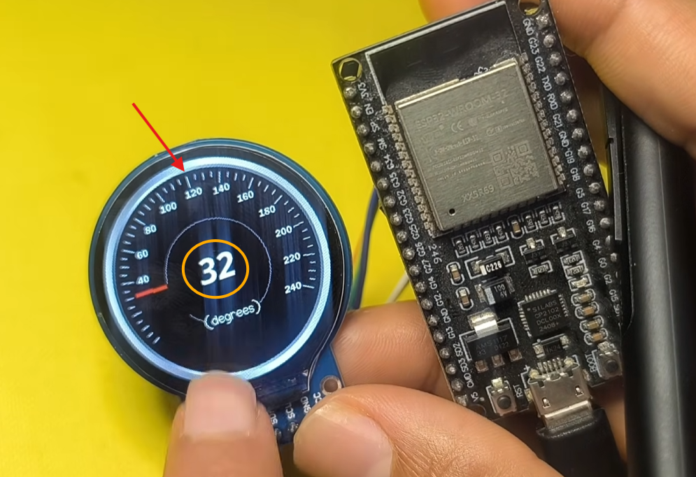
2. Animated Dial (Sprites + Smooth Animation)
Want your project to look “alive”? An animated dial with a rotating needle that moves in response to a changing value. This is perfect for loading screens, progress indicators, or basic gauges.
🚀 Conclusion
The GC9A01 round display unlocks a new level of creativity in electronics. With the right setup and optimization, you can build smooth, professional-looking interfaces that rival commercial devices.
The ESP32 provides the processing power and connectivity (WiFi/Bluetooth), while the TFT_eSPI The library unlocks the full potential of the beautiful round display.
Whether you are building a smart watch, a weather station, or just a cool desk toy, mastering this setup gives you a powerful foundation. The key takeaway is to respect the configuration—the User_Setup.h file is the heart of the operation. Get that right, and the rest is just creativity.