Arduino Password Door Lock System – DIY Project
Building a password-protected door lock system with Arduino is a great beginner-to-intermediate electronics project. You will learn how to create a secure digital door lock using an Arduino, a 4×4 keypad, an I2C LCD, a buzzer, and a solenoid door lock.
The system allows a user to enter a password through the keypad. If the password is correct, the door lock opens for a few seconds. If the password is incorrect multiple times, the system temporarily blocks access and activates a buzzer alarm.
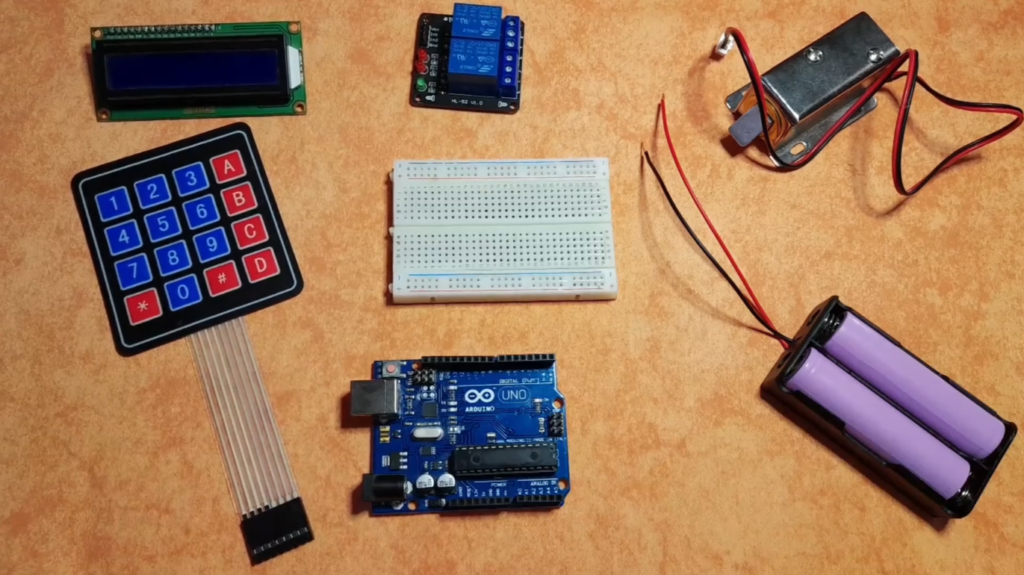
📦 Components Required
To build this project, you will need the following components:
- Arduino Uno (or compatible board)
- LCD Display 16×2 (with I2C adapter – highly recommended to save pins)
- 4×4 Keypad Matrix
- Solenoid Door Lock
- Relay Module or NPN Transistor (to drive the lock)
- Buzzer (Optional)
- Jumper wires
- Breadboard
- Power supply
I highly recommend getting a complete starter kit that includes everything you need to create a wide range of projects.
🔌 Circuit Connections
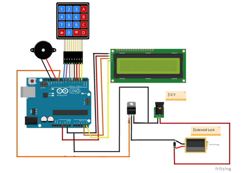
Here’s how to connect all the components:
Keypad Connections:
- Row pins (9,8,7,6) → Arduino pins 9,8,7,6
- Column pins (5,4,3,2) → Arduino pins 5,4,3,2
I2C LCD Connections:
- SDA → Arduino A4
- SCL → Arduino A5
- VCC → 5V
- GND → GND
Output Devices:
| Component | Arduino Pin |
|---|---|
| Solenoid Lock (via relay/transistor) | 11 |
| Buzzer | 12 |
⚠️ Important:
The solenoid lock must NOT be powered directly from the Arduino pin. Always use a relay module or transistor with external power.
💻 Arduino Code
Here is the complete Arduino code for the password door lock system.
// Include LCD display library for I2C
#include <LiquidCrystal_I2C.h>
// Include Keypad library
#include <Keypad.h>
// Password Length
const int Password_Length = 7;
// String to hold password input
String Data;
// Put The Right Password
String Master = "1234567";
// Pin connected to lock (relay OR Transistor)
const int lockOutput = 11;
// Pin connected to Buzzer
const int buzzerPin = 12;
// Counter for character entries
byte data_count = 0;
// Counter for number of tries
byte tries_count = 0;
// Character to hold key input
char customKey;
// Constants for row and column sizes
const byte ROWS = 4;
const byte COLS = 4;
// Array to represent keys on keypad
char hexaKeys[ROWS][COLS] = {
{ '1', '2', '3', 'A' },
{ '4', '5', '6', 'B' },
{ '7', '8', '9', 'C' },
{ '*', '0', '#', 'D' }
};
// Connections to Arduino
byte rowPins[ROWS] = { 9, 8, 7, 6 };
byte colPins[COLS] = { 5, 4, 3, 2 };
// Create keypad object
Keypad customKeypad = Keypad(makeKeymap(hexaKeys), rowPins, colPins, ROWS, COLS);
// Create LCD object : Use 0x27 If 0x3F Doesn't work
LiquidCrystal_I2C lcd(0x3F, 16, 2);
void setup() {
// Setup LCD with backlight and initialize
lcd.init();
lcd.backlight();
// Set lockOutput, buzzer as an OUTPUT pin
pinMode(lockOutput, OUTPUT);
pinMode(buzzerPin, OUTPUT);
}
void loop() {
// Initialize LCD and print
lcd.setCursor(0, 0);
lcd.print("Enter Password:");
// Look for keypress
customKey = customKeypad.getKey();
if (customKey) {
// Enter keypress into array and increment counter
Data += customKey;
lcd.setCursor(data_count, 1);
lcd.print(Data[data_count]);
data_count++;
// Key Press Sound Effect
digitalWrite(buzzerPin, HIGH);
delay(50);
digitalWrite(buzzerPin, LOW);
}
// See if we have reached the password length
if (data_count == Password_Length) {
tries_count++;
lcd.clear();
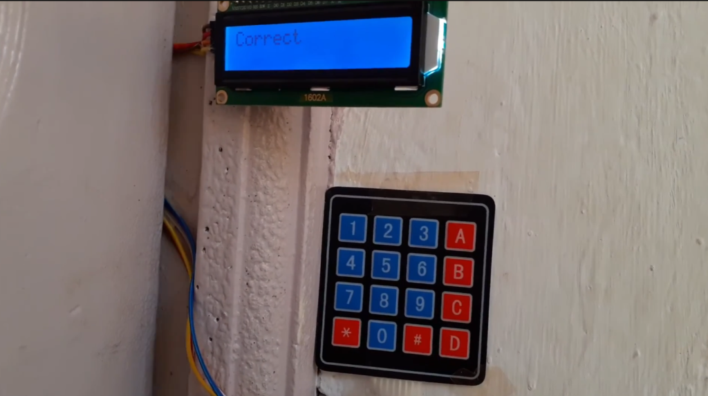
if (Data == Master) {
// Correct Password
lcd.print("Correct Password");
lcd.setCursor(0, 1);
lcd.print("Please Enter Sir");
delay(500);
// Open Door Lock for 5 seconds
digitalWrite(lockOutput, HIGH);
delay(5000);
digitalWrite(lockOutput, LOW);
//Reset tries_count
tries_count = 0;
} else {
// Incorrect Password
if (tries_count >= 3) {
for (int i = 0; i < 20; i++) {
lcd.clear();
lcd.print("Try in: " + String(20 - i));
lcd.setCursor(0, 1);
lcd.print("Seconds");
digitalWrite(buzzerPin, HIGH);
delay(500);
digitalWrite(buzzerPin, LOW);
delay(500);
}
//Reset tries_count
tries_count = 0;
} else {
//Wrong Password Sound Effect
digitalWrite(buzzerPin, HIGH);
delay(500);
digitalWrite(buzzerPin, LOW);
lcd.print("Wrong Password");
delay(1500);
}
}
// Clear data and LCD display
lcd.clear();
clearData();
}
}
void clearData() {
//Reset data_count
data_count = 0;
//Reset Data
Data = "";
}
🎯 Testing and Troubleshooting
Libraries Used:
Two libraries are used in this project.
- Keypad Library → reads keypad button presses.
- LiquidCrystal_I2C Library → controls the LCD through the I2C interface.
Before uploading, make sure to install these libraries from the Arduino Library Manager:
Uploading the Code:
- Connect your Arduino board to your computer.
- Open Arduino IDE.
- Install the required libraries.
- Copy and paste the code.
- Select your board and port.
- Click Upload.
Once uploaded, you can attach the solenoid lock to your door and start testing.
Common Issues and Solutions:
- LCD not displaying anything?
- Check the I2C address (try 0x27 instead of 0x3F)
- Verify SDA and SCL connections
- Adjust the potentiometer on the I2C module for contrast
- Keypad not responding?
- Double-check row and column pin assignments
- Ensure no loose connections
- Test each key with a simple sketch first
- Solenoid not locking?
- Verify external power supply (12V for solenoid)
- Check relay connections
- Ensure the transistor/relay can handle the current
🧠 Code Explanation
1️⃣ Password Storage:
The right password is stored in the variable:
String Master = "1234567";
You can change this password to anything you want.
2️⃣ Reading Keypad Input:
The keypad reads user input using:
  // Look for keypress
  customKey = customKeypad.getKey();
Every pressed key is added to the Data string.
3️⃣ Password Verification:
Once the entered characters reach the password length:
if (Data == Master)
The system compares the entered password with the stored one.
If the password is correct ✅:
digitalWrite(lockOutput, HIGH);
delay(5000);
digitalWrite(lockOutput, LOW);
The solenoid lock activates for 5 seconds, allowing the door to open.
If the Password is wrong 🔄:
- Failed Attempt Tracking: The system counts incorrect attempts using
tries_count - Lockout Mechanism: After 3 failed attempts, the system enters a 20-second cooldown period
- Audible Feedback: The buzzer provides different sounds for keypresses, correct/incorrect passwords, and lockout warnings
4️⃣ User Interface:
The LCD provides clear feedback:
- “Enter Password:” prompt on the first line
- Asterisks (*) show as you type (though in this version, it shows the actual characters)
- Success or failure messages
- Countdown timer during lockout
🚀 Possible Improvements
Once you have the basic system working, try these interesting modifications:
- Add an EEPROM to store multiple user passwords
- Include an RFID reader as a secondary authentication method
- Add a real-time clock for time-based access
- Create a logging system to track access attempts
- Add a Bluetooth module for remote control and password changes
Final Thoughts
This Arduino password door lock system is an excellent project that combines multiple concepts: user input, display output, password authentication, and physical actuation. It’s practical, expandable, and teaches valuable lessons about security system design.
The code is well-structured and includes important security features like the lockout mechanism after failed attempts. Whether you’re building this for a school project, to secure a cabinet, or just for learning, it’s a rewarding build that results in a functional security device.
Happy building, and stay secure!
Projects like this are also a great introduction to smart home systems.