Build a Powerful ESP32 LED Controller App with RemoteXY (No Coding Required!)
Controlling Devices from your smartphone is one of the coolest ways to explore IoT.
In this Guide, you’ll learn how to create a powerful controller app using an ESP32/ESP8266 board. Thanks to RemoteXY, you can create a fully functional, beautiful control interface for your ESP32 in minutes—without writing a single line of app code.
Before We Begin: If you’re completely new to the ESP32, I recommend checking out my previous blog post, an Ultimate ESP32 Beginner’s Guide. We’ve covered the basics of setting up your development environment, installing board support, and uploading your first program.
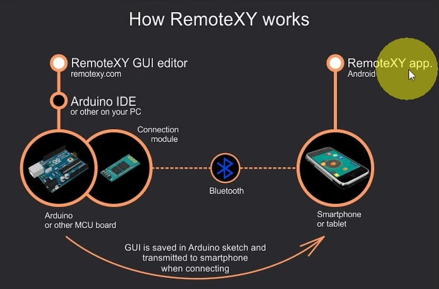
🧠 What is RemoteXY?
RemoteXY is an online service that allows you to create a custom graphical user interface (GUI) for your microcontroller projects using a simple drag-and-drop editor. It generates the C++ code for you, which you then upload to your board. The RemoteXY mobile app (available for both iOS and Android) connects to your device via Bluetooth or WiFi, giving you a professional-looking remote control
👉 It eliminates the need to build apps from scratch!

🧰 Components Required
- ESP32 Development Board or ESP8266 (NodeMCU)
- LED or Relay to control high-voltage devices
- 220Ω Resistor (Protects LED)
- Breadboard & Jumper wires
- Smartphone (Android/iOS)
I highly recommend getting a complete ESP32 starter kit.
It will save you time, money, and frustration—and help you learn IoT much faster.
🔌 Circuit Diagram (ESP32/ESP8266)
Before diving into the software, let’s get the hardware ready:
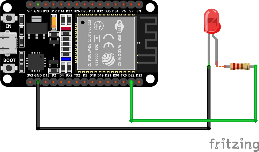
Connections:
- Connect the anode (long leg) of the LED to one end of the 220Ω resistor
- Connect the other end of the resistor to any GPIO pin (D22) on the ESP32 / (D5) on the ESP8266
- Connect the cathode (short leg) to the GND of the Board
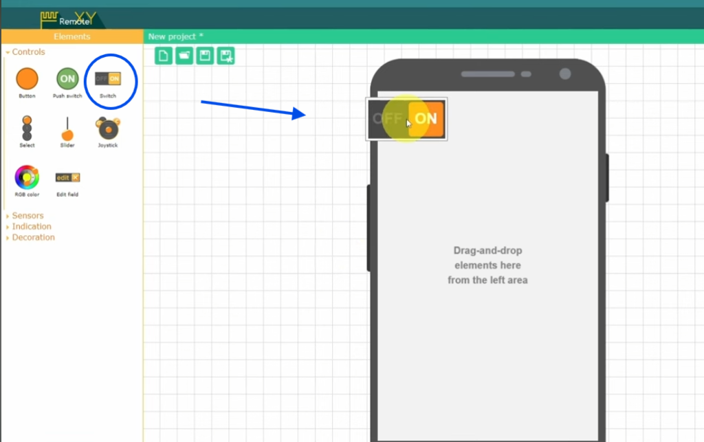
🛠 Step 1: Create the App Interface
This is the fun part. We’ll create a switch to control the LED or a Device like a lamp:
- Go to the Editor: Open your browser and navigate to the RemoteXY Editor.
- Add a Switch: From the left toolbar, find the Switch element and drag it onto the mock smartphone screen. This will control your external LED.
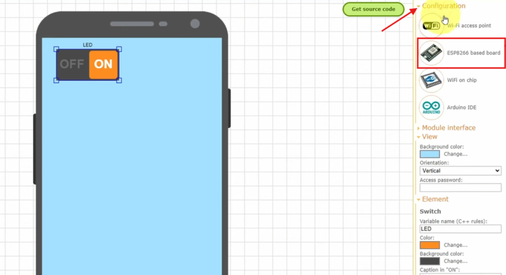
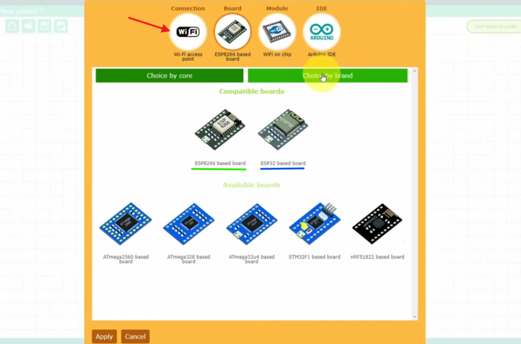
- Configure the Project: Click on the Configuration tab in the right toolbar. A settings window will pop up. Set the following options and click “Apply” :
- Connection:
Wifi Access Point - Board:
ESP32 or ESP8266 based board - Module: Integrated
Wifi on chip - IDE:
Arduino IDE
- Connection:
- Get back to the RemoteXY editor, select the switch, and “Snap to Pin” (22 or D5)
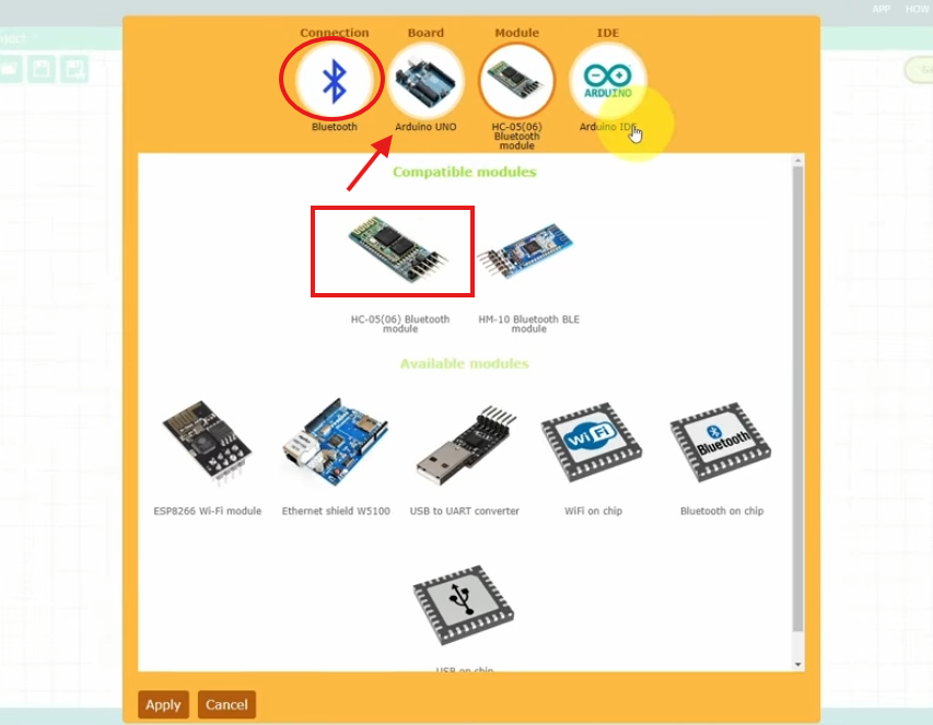
In addition to Wi-Fi control using ESP8266/ESP32, RemoteXY also supports Bluetooth with an Arduino board. Here are the settings for that:
🧾 Step 2: Getting the Code
Now, let’s get the automatically generated code:
- Click the green “Get source code” button in the top right corner of the editor. Download the generated Arduino sketch.
- Open the Sketch: Unzip the downloaded file and open the project
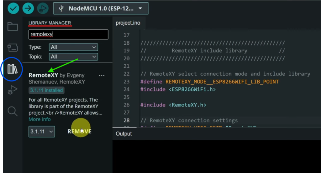
.inofile in your Arduino IDE. - You’ll need the “RemoteXY library” for the Arduino IDE. Download it from the RemoteXY website or install it via the Library Manager
Here’s a complete working example:
#define REMOTEXY_MODE__WIFI_POINT

#include <WiFi.h>
// RemoteXY connection settings
#define REMOTEXY_WIFI_SSID "RemoteXY"
#define REMOTEXY_WIFI_PASSWORD "12345678"
#define REMOTEXY_SERVER_PORT 6377


#include <RemoteXY.h>

// RemoteXY GUI configuration
#pragma pack(push, 1)
uint8_t const PROGMEM RemoteXY_CONF_PROGMEM[] =   // 37 bytes V19
  { 255,1,0,0,0,30,0,19,0,0,0,0,31,1,106,200,1,1,1,0,
  2,17,7,44,22,0,2,26,31,31,79,78,0,79,70,70,0 };

// this structure defines all the variables and events of your control interface
struct {

    // input variables
  uint8_t switch_01; // =1 if switch ON and =0 if OFF, from 0 to 1

    // other variable
  uint8_t connect_flag;  // =1 if wire connected, else =0

} RemoteXY;
#pragma pack(pop)

/////////////////////////////////////////////
//           END RemoteXY include          //
/////////////////////////////////////////////

#define PIN_SWITCH_01 22


void setup()
{
  RemoteXY_Init ();  // initialization by macros

  pinMode (PIN_SWITCH_01, OUTPUT);

  // TODO you setup code

}

void loop()
{
  RemoteXYEngine.handler ();

  digitalWrite(PIN_SWITCH_01, (RemoteXY.switch_01==0)?LOW:HIGH);

  // TODO you loop code
  // use the RemoteXY structure for data transfer
  // do not call delay(), use instead RemoteXYEngine.delay()

}
📲 Step 3: Upload & Connect
Uploading to the ESP32
- Connect your ESP32 to your computer via USB.
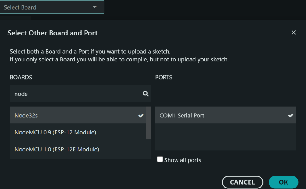
- In the Arduino IDE, select the correct board (e.g.,
ESP32 Dev ModuleorESP32S3 Dev Module) and the correct COM port. - Click the Upload button (right arrow icon).
Connecting from Your Phone
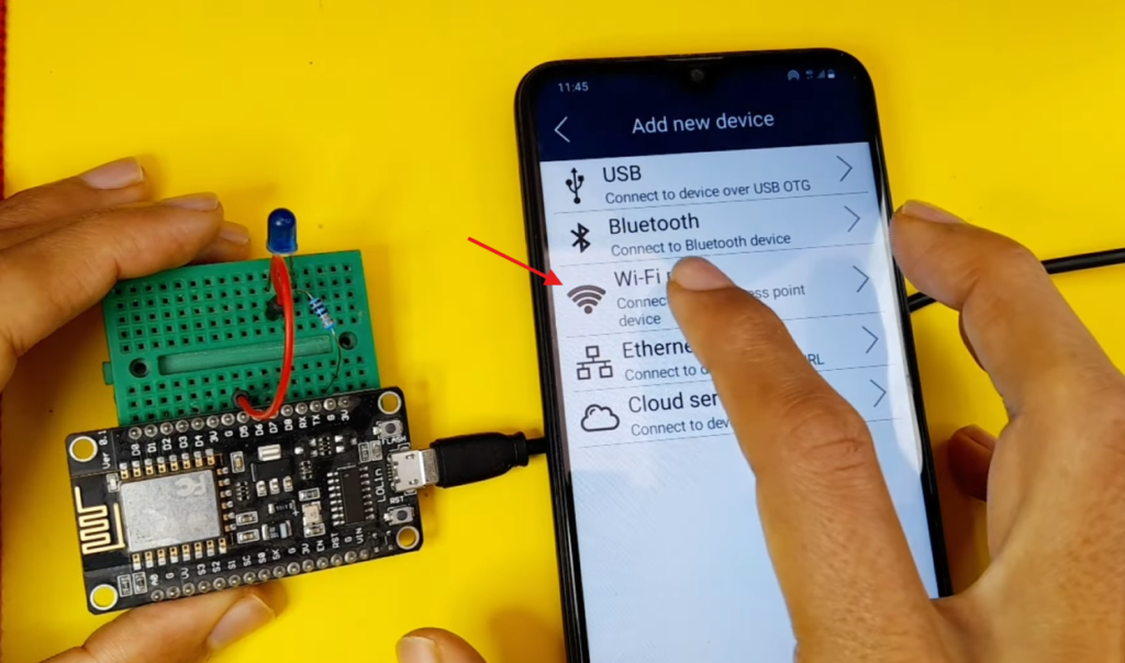
- Ensure WiFi is enabled on your smartphone.
- Install and open the RemoteXY app (FREE).
- Tap the
+(Plus) button in the top navigation bar. - Select Wi-Fi Point.
- Your device (e.g., “RemoteXY”) should appear in the list.
- Tap on it to connect (Password: 12345678)
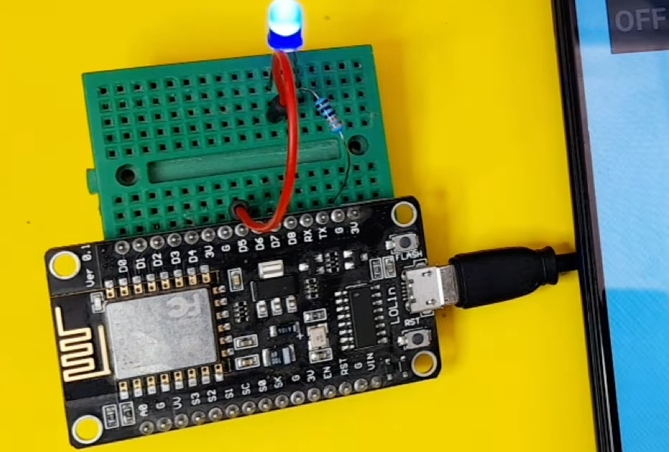
You should now see your custom interface! Toggle the switch to turn the external LED on/off.
🎉 You can now control your LED wirelessly!
🧠 Understanding the Generated RemoteXY Code
This code is automatically generated by RemoteXY, but understanding it helps you customize and extend your project.
🔌 1. Connection Mode Definition
#define REMOTEXY_MODE__WIFI_POINT
👉 This line sets the connection type.
WIFI_POINT= ESP creates its own Wi-Fi network (Access Point)- Your phone connects directly to the ESP
📌 In my case:
- Wi-Fi Name → RemoteXY
- Password → 12345678
📡 2. Wi-Fi Settings
#include <WiFi.h>
// RemoteXY connection settings
#define REMOTEXY_WIFI_SSID "RemoteXY"
#define REMOTEXY_WIFI_PASSWORD "12345678"
#define REMOTEXY_SERVER_PORT 6377
WiFi.h→ Enables Wi-Fi features (ESP32)SSID→ Name of the ESP networkPASSWORD→ Network passwordPORT→ Communication port between app and ESP
📌 The mobile app connects using these settings.
📚 3. RemoteXY Library
#include <RemoteXY.h>
👉 This library handles:
- Communication between the app and the ESP
- Data transfer (buttons, sliders, etc.)
- Interface synchronization
🧩 4. GUI Configuration Data
uint8_t const PROGMEM RemoteXY_CONF_PROGMEM[] = { ... }; 👉 This array contains:
- Your app design (buttons, switches, sliders)
- Layout and behavior of UI elements
🧱 5. Interface Structure
struct {
  uint8_t switch_01;
  uint8_t connect_flag;
} RemoteXY;
👉 This structure is the bridge between your app and code
📦 6. Pin Definition
#define PIN_SWITCH_01 22
👉 This defines the ESP32 pin connected to your LED.
⚙️ 7. Setup Function
void setup()
{
  RemoteXY_Init ();
  pinMode (PIN_SWITCH_01, OUTPUT);
}
RemoteXY_Init()
👉 Initializes communication with the mobile apppinMode()
👉 Sets pin 22 as output (for LED control)
🔁 8. Main Loop
void loop()
{
  RemoteXYEngine.handler ();

  digitalWrite(PIN_SWITCH_01, (RemoteXY.switch_01==0)?LOW:HIGH);
}
👉 This keeps communication running and updating values from the app in real-time
digitalWrite(PIN_SWITCH_01, (RemoteXY.switch_01==0)?LOW:HIGH);
👉 This line controls the LED based on the app switch:
✨ Features You Can Add
- RGB LED control
- Multiple LEDs
- Voice control integration
- Scheduling (auto ON/OFF)
- Internet control (from anywhere)
🧩 Troubleshooting
- ❌ Not connecting? → Check Wi-Fi credentials
- ❌ LED not working? → Verify the GPIO pin
- ❌ App not responding? → Restart ESP
📌 Conclusion
You’ve just built a powerful ESP LED controller app using RemoteXY — combining hardware and mobile control without writing any app code.
This is just the beginning of your IoT journey 🚀