Raspberry Pi GPIO Inputs: Working with Sensors Step by Step
Let’s take the next step in our Raspberry Pi GPIO journey by working with sensors. Instead of only controlling devices like LEDs, we’ll learn how to read inputs from the real world and make our projects react automatically.
1️⃣ What Are Sensors?
Sensors are components that detect changes in the environment and send signals to the Raspberry Pi. These signals are read through the GPIO input pins.
Common examples include:
- Detecting gas or smoke
- Detecting motion or obstacles
- Detecting a button press
In most cases, sensors send either:
- HIGH (3.3V) → active
- LOW (0V) → inactive
2️⃣ Before We Start (Requirements)
This guide assumes you already have a basic understanding of Raspberry Pi GPIO basics.
If you haven’t read it yet, I highly recommend starting with the first GPIO guide. It will make this post much easier to follow and help you avoid common mistakes.
👉 Read the first guide: Getting Started with Raspberry Pi GPIO Pins
You’ll need:
- Raspberry Pi with Raspberry Pi OS
- Python 3
- Breadboard and jumper wires
- Gas sensor module (MQ‑series or similar)
- IR sensor module
- Push buttons
- Optional: LED or buzzer for feedback
3️⃣ Using GPIO Pins as Inputs
To understand how to use Sensors, let’s work with a few examples, covering three popular and beginner-friendly sensors:
- Gas leakage sensor
- IR (Infrared) sensor
- A Push button (Switch)
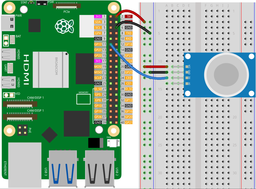
Step 1: Connect Your Sensor
Most sensors, like the MQ-5 Gas Sensor, IR-Sensor, have 3 or 4 pins:
- VCC → 3.3V or 5V on the Raspberry Pi
- GND → Ground (GND) pin on the Pi
- DO (Digital Output) – HIGH/LOW signal when gas exceeds threshold
- AO (Analog Output) – Voltage proportional to gas concentration
⚠ Important: Raspberry Pi cannot read analog voltage directly. If you want analog readings, you’ll need an ADC (analog-to-digital converter).
✅ For simplicity, we’ll only use digital output (DO): DO → GPIO17 (or any GPIO pin you prefer)
💡 This setup works for digital-output sensors like MQ-2 gas sensors or simple IR sensors.
Step 2: Python Code to Read Sensors
Open the Thonny Python IDE on your Raspberry Pi. Once it’s open, create a new file and paste the gas sensor code into the editor:
import RPi.GPIO as GPIO
import time

# Setup
GPIO.setmode(GPIO.BCM)
SENSOR_PIN = 17
GPIO.setup(SENSOR_PIN, GPIO.IN)

try:
    while True:
        if GPIO.input(SENSOR_PIN)==0:
            print("Gas leakage detected!")
        else:
            print("Gas levels normal.")
        time.sleep(0.5)

except KeyboardInterrupt:
    GPIO.cleanup()
After that, save your file with a name like gas_sensor.py, and you’re ready to run it directly from Thonny. This makes it simple to see the output in the built-in terminal and make changes if needed.
Let’s explain the code step by step so you understand what each part does and how it makes the sensor work.
Import Libraries & GPIO Setup
import RPi.GPIO as GPIO
import timeRPi.GPIO: This library allows Python to interact with the Raspberry Pi’s GPIO pins.time: Provides timing functions likesleep(), which we use to pause between sensor readings.
GPIO.setmode(GPIO.BCM)
SENSOR_PIN = 17
GPIO.setup(SENSOR_PIN, GPIO.IN)GPIO.setmode(GPIO.BCM): Tells the Raspberry Pi we’ll use the BCM numbering system for GPIO pins (GPIO numbers, not pin numbers on the header).SENSOR_PIN = 17: Assigns GPIO17 to a variable so it’s easier to reference later.GPIO.setup(SENSOR_PIN, GPIO.IN): Configures GPIO17 as an input pin, so it can read signals from the gas sensor.
⚡ Some Digital sensors send LOW (0) when triggered and HIGH (1) when normal.
Main Loop: Reading Sensor Data
try:
    while True:
        if GPIO.input(SENSOR_PIN):
            print("⚠ Gas leakage detected!")
        else:
            print("Gas levels normal.")
        time.sleep(0.5)

except KeyboardInterrupt:
GPIO.cleanup()try:: Starts a block of code where we can safely catch exceptions, like stopping the program with Ctrl+C ( to runGPIO.cleanup(): which resets all GPIO pins to a safe state)while True:: A loop that runs forever, continuously checking the sensor.GPIO.input(SENSOR_PIN): Reads the current state of the sensor pin:- Returns
False/ LOW(0) if gas is detected - Returns
True/ HIGH(1) if levels are normal
- Returns
print(): Displays a message in the terminal for each state.time.sleep(0.5): Pauses for 0.5 seconds to prevent flooding the terminal with messages and to give the sensor a small delay between readings.
💡 This simple loop is enough for basic monitoring. You could later trigger an LED or buzzer when gas is detected.
Step 3: Swap in the IR Sensor
If you want to use other sensors like the IR Obstacle avoiding sensor or any similar ones you could:
- Replace the gas sensor with a digital IR sensor. Keep VCC, GND, and GPIO17 the same.
- No need to change the Python code; just update the printed message if you want:
import RPi.GPIO as GPIO
import time

# Setup
GPIO.setmode(GPIO.BCM)
SENSOR_PIN = 17
GPIO.setup(SENSOR_PIN, GPIO.IN)

try:
    while True:
        if GPIO.input(SENSOR_PIN):
            print("Obstacle detected by IR sensor!")
        else:
            print("Path is clear.")
        time.sleep(0.5)

except KeyboardInterrupt:
    GPIO.cleanup()
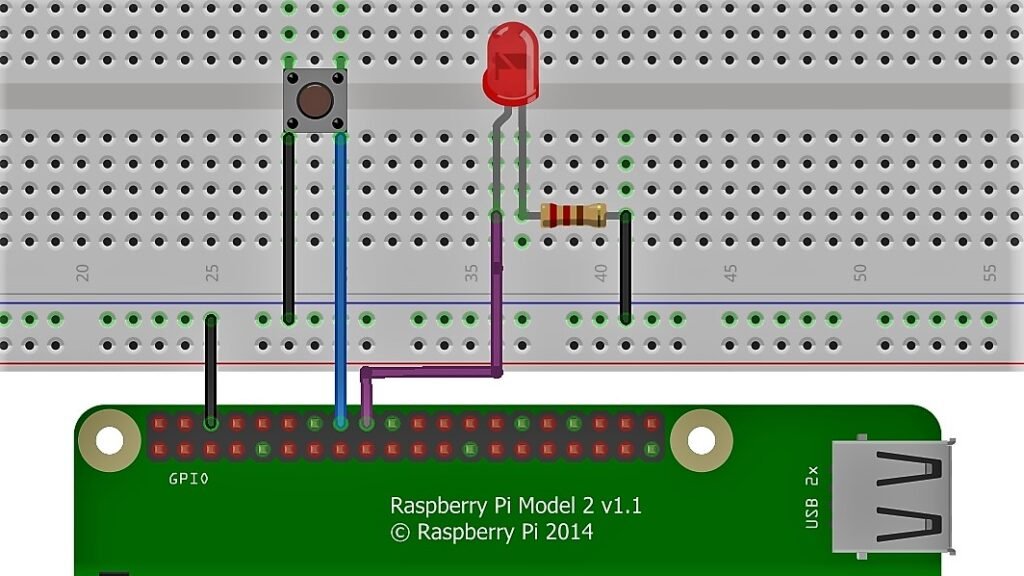
4️⃣Using a Push Button (Switch)
Unlike sensors like the gas leakage or IR sensor, which automatically provide a HIGH or LOW signal depending on the environment, a push button doesn’t generate a signal on its own. It simply connects or disconnects a circuit when pressed. Because of this, the Raspberry Pi can’t know the button’s state unless we guide it.
This is where the pull-up resistor comes in. By enabling the Pi’s internal pull-up resistor, the button’s input pin is kept HIGH when the button is not pressed. When you press the button, it connects the pin to GND, making the pin read LOW.
🚨 Schematics:
Code:
import RPi.GPIO as GPIO
import time

# Setup
GPIO.setmode(GPIO.BCM)
BUTTON_PIN = 23
LED_PIN = 24

GPIO.setup(BUTTON_PIN, GPIO.IN, pull_up_down=GPIO.PUD_UP)
GPIO.setup(LED_PIN, GPIO.OUT)

try:
    while True:
         if GPIO.input(BUTTON_PIN) == False:
             GPIO.output(LED_PIN , True)
             print('Button Pressed...')
         else:
             GPIO.output(LED_PIN , False)
         time.sleep(0.2)
except:
    GPIO.cleanup()
How It Works
GPIO.setup(BUTTON_PIN, GPIO.IN, pull_up_down=GPIO.PUD_UP):
Configures the button pin as input with an internal pull-up resistor. This keeps the pin HIGH when the button isn’t pressed.if GPIO.input(BUTTON_PIN) == False:
Detects when the button is pressed (connected to GND, so pin reads LOW).GPIO.output(LED_PIN, GPIO.HIGH/LOW)
Turns the LED on or off depending on the button state.
✅ This is a simple example of using a push button as a digital input to control an output (LED), and the same technique can be used to trigger other devices like buzzers or motors.